
Manual

IQ-INT II IQ Interface
Page 8
Reference Manual
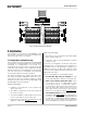
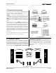
Fig. 3.5 IQ-INT II Output Connection to RJ45 Input.
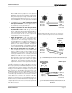
Fig. 3.6 RJ45 Output Connection to a IQ-INT-II.
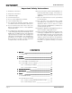
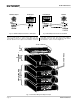
Fig. 3.7 Crown Bus Wiring from Output to Input.
IQ-INT II Output
RJ45 Input
IQ-INT II
RJ45 Output
The IQ components on each Crown Bus loop are
connected in succession. Each loop begins and ends
with the
IQ-INT II
. The output of the interface connects
to the input of the first unit, then each unit’s output is
connected to the next unit’s input until the loop returns
to the interface. This is shown in Figure 3.7.
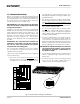
AMPLIFIERS WITH
IQ–PIP MODULES
IQ
PROCESSOR /
MIXER
IQ-INT II
CROWN BUS
P
O
W
E
R
IN
1
O
U
T
IN
2
O
U
T
IN
3
O
U
T
IN
4
O
U
T
IN
5
O
U
T
IN
6
O
U
T
IN
7
O
U
T
IN
8
O
U
T
C
O
M
P
U
T
E
R
TO HOST COMPUTER