
Manual

IQ-INT II IQ Interface
Page 9
Reference Manual
1
2
3
4
5
6
7
8
9
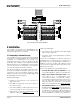
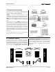
Refer to the documentation
provided with your RS422
interface to identify the
correct pin connections.
Transmit Data (TXD
+
)
Transmit Data (TXD
–
)
Receive Data (RXD
–
)
Receive Data (RXD
+
)
Signal Ground (GND)
Clear to Send (CTS
–
)
Clear to Send (CTS
+
)
Request to Send
(RTS
+
)
Request to Send
(RTS
–
)
PIN
The female interface connector is shown as it appears.
IQ-INT II
15
69
PC (RS422)
51
96
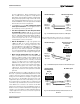
Fig. 3.8 Standard RS232 Wiring
Fig. 3.9 RS422 Wiring
3.2 Connecting to a Host Computer
There are two main communication standards supported
by the
IQ-INT II
for serial communication with a host
computer. They are RS232 and RS422.
RS232 is commonly used with IBM
®
PCs and
compatibles. Because it uses unbalanced signal wiring,
it cannot be used for distances over 50 feet (15.2 m).
RS422 uses balanced signal wiring and can be used
for distances up to 2,000 feet (610 m) with data grade
cable.
Although not very common, RS423 communication can
also be used. It is a hybrid of RS232 and RS422 that
uses the unbalanced transmitter (TXD) wiring of RS232
and the balanced receiver (RXD) wiring of RS422. It
provides signal ground isolation between the transmit
and receive lines. With a proper cable, it can be used
over a greater distance than RS232, but over a shorter
distance than RS422. Contact the Crown Technical
Support Group if you want to use RS423 and need more
information.
The following illustrations show how to connect the
IQ-
INT II
to the most common host serial ports:
Not used
ReceiveData (RXD)
Transmit Data (TXD)
Signal Ground (GND)
Request to Send (RTS)
Clear to Send (CTS)
2
3
5
7
8
2
3
5
7
8
Transmit Data (TXD)
Receive Data (RXD)
Signal Ground (GND)
Clear to Send (CTS)
Request to Send (RTS)
PIN PIN
Cable connectors are numbered as they appear from the front.
PC (RS232)
IQ-INT II
51
96
1,4,6,9
51
9
6
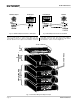
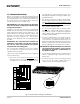
3.2.1 Connecting to a Modem
The
IQ-INT II
is also modem compatible. The
IQ-INT II
periodically sends out an “AT” command string {ATS0=1}
that automatically initializes a connected modem to its
max baud rate and auto-answer mode. A standard null
modem cable should be used between the interface
and modem with the exception of pin 4. Pin 4 of the 9-
pin RS232/242 connector on the back of the interface
should NOT be connected. This pin implements one
side of the RS422 type line receiver and, as such, allows
balanced wiring on a 9-pin connector. This configuration
is not compatible with some 232/null modem
applications. Refer to the diagram below for modem
wiring detail.
IQ INTERFACE
MODEM
9-PIN CABLE
MALE MALE
11
22
33
4
(MUST BE DISABLED)
4
55
66
77
88
99
STANDARD
9-PIN NULL MODEM
FEMALE MALE
11
22
33
44
55
66
77
88
99
9-PIN to 25-PIN
CABLE
FEMALE MALE
18
23
32
420
57
66
74
85
922
Fig. 3.10 Modem Hookup