- MSD Turbo Advanced IQ Software for IQ System Control and Monitoring with an MS-DOS PC Host Computer Version 1.4 © 1996 by Crown International, Inc., P.O. Box 1000, Elkhart, IN 46515-1000 U.S.A. Telephone: 219-294-8000. Fax: 219-294-8329. IQ System components and software are produced by the Professional Audio Division of Crown International, Inc.
IQ–MSD Turbo 1.4 Advanced IQ System Software Crown Software License Agreement This is a legal agreement between you, the end user, and Crown, a division of Crown International, Inc., 1718 West Mishawaka Road, Elkhart, Indiana 46517-4095 U.S.A. If you do not agree to the terms of this agreement, promptly return the unopened disk package and the accompanying items (including written materials and binders or other containers) to the place you obtained them for a refund. License 1.
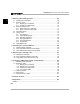
IQ–MSD Turbo 1.4 Advanced IQ System Software Contents C 1 Introducing IQ–MSD Turbo ................................................................................ 11 1.1 1.2 1.3 1.4 1.5 1.6 System Requirements ............................................................................................................... About This Manual ................................................................................................................... Technical Support .................................
IQ–MSD Turbo 1.4 Advanced IQ System Software 3 Designing Graphics Plates ................................................................................ 45 C 3.1 Overview ................................................................................................................................. 3.1.1 A Simple Example ....................................................................................................... 3.1.2 Graphics Plate Design Principles ........................................
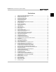
IQ–MSD Turbo 1.4 Advanced IQ System Software 5 Monitoring & Controlling Amplifiers ............................................................... 115 5.1 5.2 5.3 5.4 5.5 Initializing an Amplifier Control Block ......................................................................................... 116 Monitoring an Amplifier ............................................................................................................. 118 5.2.1 Monitoring from a Control Block ..........................
IQ–MSD Turbo 1.4 Advanced IQ System Software 8 Monitoring & Controlling Drones ................................................................... 169 C 8.1 8.2 8.3 8.4 8.5 8.6 Initializing a Drone Control Block ............................................................................................. 169 Monitoring a Drone ................................................................................................................ 170 8.2.1 Monitoring from a Control Block .......................
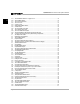
IQ–MSD Turbo 1.4 Advanced IQ System Software Illustrations 1.1 2.1 2.2 2.3 2.4 2.5 2.6 2.7 2.8 2.9 2.10 2.11 2.12 2.13 2.14 2.15 2.16 2.17 2.18 2.19 2.20 2.21 2.22 2.23 2.24 2.25 2.26 2.27 2.28 2.29 2.30 3.1 3.2 3.3 3.4 3.5 3.6 3.7 3.8 3.9 3.10 3.11 3.12 3.13 3.14 3.15 3.16 3.17 3.18 A Sample Turbo Graphics Plate Showing Custom Objects .............................................................................. 11 Sample Text Screen and Graphics Plate ....................................................
IQ–MSD Turbo 1.4 Advanced IQ System Software C 3.19 3.20 3.21 3.22 3.23 3.24 3.25 3.26 3.27 3.28 3.29 3.30 4.1 4.2 4.3 4.4 4.5 4.6 4.7 4.8 4.9 4.10 4.11 4.12 4.13 4.14 4.15 4.16 4.17 4.18 4.19 4.20 4.21 4.22 4.23 4.24 4.25 4.26 4.27 4.28 4.29 4.30 4.31 4.32 4.33 4.34 4.35 4.36 4.37 4.38 4.39 Page 8 The GDM Attributes Window for a Legacy IQ P.I.P. ........................................................................................ 59 The Pot Attributes Window .........................................
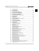
IQ–MSD Turbo 1.4 Advanced IQ System Software 4.40 4.41 4.42 4.43 4.44 4.45 4.46 4.47 4.48 4.49 4.50 4.51 4.52 4.53 4.54 4.55 4.56 4.57 4.58 4.59 4.60 5.1 5.2 5.3 5.4 5.5 5.6 5.7 5.8 5.9 5.10 5.11 5.12 5.13 6.1 6.2 6.3 6.4 6.5 6.6 6.7 6.8 6.9 6.10 6.11 6.12 6.13 6.14 6.15 6.16 6.17 The Select Mini Plate Window ...................................................................................................................... 102 The Line Attributes Window .................................................
IQ–MSD Turbo 1.4 Advanced IQ System Software C 6.18 7.1 7.2 7.3 7.4 8.1 8.2 8.3 8.4 8.5 8.6 8.7 8.8 8.9 8.10 8.11 8.12 8.13 9.1 9.2 10.1 10.2 11.1 11.2 11.3 11.4 11.5 11.6 The Fifth AMB-5 Sub-block Screen ............................................................................................................... 159 A Typical Equalizer Control Block Screen ....................................................................................................
IQ–MSD Turbo 1.4 Advanced IQ System Software O R O AU D I C ONT L 1 1 Introducing IQ–MSD Turbo O W N Welcome to the Crown IQ–MSD Turbo program—software that brings the powerful monitor and control capabilities of your IQ audio system to your PC-compatible computer. This manual will describe the use of version 1.4 of IQ–MSD Turbo, referred from here on simply as Turbo. With Turbo you can monitor and control your audio system from a remote location.
IQ–MSD Turbo 1.4 Advanced IQ System Software 1.1 System Requirements • A 33 MHz Intel® 80486 PC-compatible computer (recommended: 75 MHz Pentium). • DOS 5.0 or higher with HIMEM.SYS and EMM386.EXE loaded. 1 • At least 8 megabytes (MB) of random-access memory (RAM) with at least 512 kilobytes (KB) of free conventional memory and no less than 3072 KB of free extended memory. • A hard disk with at least 5 MB of free space. • A VGA 16-color display adapter or better.
IQ–MSD Turbo 1.4 Advanced IQ System Software The typographical conventions used in this manual are listed below: Style Meaning Bold Indicates important passages which should be read. It also indicates an important keyword or keyphrase. Bold Italics Indicates a helpful tip. Italics Indicates a note. It is also used to emphasize a word or tradename. T y p e w r i t e r Indicates something that should be typed exactly as shown.
IQ–MSD Turbo 1.4 Advanced IQ System Software 1.4 Installation 1 Turbo is a DOS-based program. Therefore, while Turbo can run under other operating systems (refer to Appendix A for information on additional operating systems such as Microsoft® Windows®), the most straightforward installation and operation is under DOS. This manual assumes that the software is being run under DOS 5.0 or 6.xx. DOS 5.0 and 6.xx use HIMEM.SYS and EMM386.EXE to manage computer memory.
IQ–MSD Turbo 1.4 Advanced IQ System Software TURBO14.PIF A sample PIF file for running Turbo under Microsoft Windows (refer to the Appendix). TURBO14.ICO An icon file that can be used with Microsoft Windows. ###.OIF Several object information files (ending with the extension OIF) are provided for various IQ2 compatible components. ###.GDM Several graphic display module files (ending with the extension GDM) are provided for various IQ2 compatible components. ###.
IQ–MSD Turbo 1.
IQ–MSD Turbo 1.4 Advanced IQ System Software M S D T U R O I Q – B 2 Using Turbo I N G The most effective way to learn Turbo is to begin using it to monitor and control an active sound system. This way you can immediately observe the effects of your commands on the system. When doing this, always use caution to avoid increasing the gain too far because hearing and loudspeaker damage can result. Turbo can also be run when the computer is not connected to an IQ System.
IQ–MSD Turbo 1.4 Advanced IQ System Software 2.1.1 Text Screens Several different types of text screens are available including Control Panel screens, Control Block screens, Display screens and Sub-block screens. The Control Panel screens contain general controls that pertain to the overall operation of Turbo such as serial port and baud rate settings. The main Control Panel screen is shown below in Figure 2.2 and is described in detail in Section 2.4 later in this manual. 2 Fig. 2.
IQ–MSD Turbo 1.4 Advanced IQ System Software Some IQ components also have one or more Display screens. A prominent feature of Display screens is their bar graph displays of signal levels. Amplifiers have two Display screens, a 6-bar and 8-bar Display screen. The amplifier Display screens show both the input and output audio signal levels for each input channel of the IQ P.I.P. Note: Only Crown P.I.P.-compatible amplifiers with an IQ P.I.P. can be controlled or monitored by the IQ System.
IQ–MSD Turbo 1.4 Advanced IQ System Software 2 2.1.2 Graphics Plates A graphics plate is a graphic screen in which custom objects can be designed and stored to create attractive operator screens for your IQ System. It may sound scary but it is actually very easy to create a graphics plate and it gives you tremendous power over your system because you decide what controls are available and in many cases what operating range the controls have.
IQ–MSD Turbo 1.4 Advanced IQ System Software 2.1.3 Perspective Figure 2.7 might help put some of the text screens and the graphics plates in perspective. It shows the relationship between control blocks, sub-blocks and graphics plates.
IQ–MSD Turbo 1.4 Advanced IQ System Software 2.2 Starting the Program Before running Turbo, first get a DOS prompt on your computer and then switch to the hard drive and directory where Turbo is stored. For example, if Turbo is stored in the “turbo” directory, use the change directory (cd) command as follows: cd \turbo. To start Turbo, type: turbo14. After a brief delay, the computer should display the title screen shown below in Figure 2.8. 2 Fig. 2.
IQ–MSD Turbo 1.4 Advanced IQ System Software /v Causes Turbo to use a default VESA-compatible graphics driver. Turbo is usually able to identify the computer’s graphics controller and use it for optimum graphics performance. Use this switch only if Turbo is unable to identify or use the graphics controller in your computer. 2.
IQ–MSD Turbo 1.4 Advanced IQ System Software It then assumes that the baud rate is not set properly and it tries to automatically detect the baud rate of the interface and configure the host computer with the same baud rate. It assumes that the interface is turned off or improperly connected if it fails to determine the baud rate. Once communication has been established with the IQ interface, Turbo begins a roll call.
IQ–MSD Turbo 1.4 Advanced IQ System Software 2.4 Setting Turbo’s System Parameters The general system controls of Turbo are located on the Control Panel screen shown in Figure 2.12. It is often necessary to make changes to these settings the first time you run Turbo because the default settings may not be correct for your system’s host computer. From a Control Block screen, press ) to go to the Control Panel screen. 2 Fig. 2.
IQ–MSD Turbo 1.4 Advanced IQ System Software this slower speed also. (Refer to the manual that came with the IQ interface for instructions on setting its baud rate.) Note: Turbo’s auto baud detect feature enables it to set the baud rate of the host computer only—not the IQ interface. Port Active: Turns the serial port on or off. When turned off, Turbo does not communicate with the IQ System, enabling you to change system settings or edit or create new dataframe files without affecting the actual IQ System.
IQ–MSD Turbo 1.4 Advanced IQ System Software current settings will be uploaded and its control block and sub-blocks updated. Note: This feature does not enable Turbo to find new IQ components that do not yet have a control block. To add new components you must either run a roll call or manually create a control block for each new component. Search Loop #: Can be used to locate a break in a particular Crown Bus loop. To use this function, first enter the Search Loop number.
IQ–MSD Turbo 1.4 Advanced IQ System Software System AUX: This control opens the System AUX Setup screen, a second type of Control Panel screen. The system AUX feature allows an external logic signal sensed by the AUX port of an IQ component to cause the IQ System settings to be either loaded (engaged) from a specified dataframe file or saved to a specified dataframe file. The System AUX Setup screen is shown below in Figure 2.13. The keyboard shortcut to it from the main Control Panel screen is A+a.
IQ–MSD Turbo 1.4 Advanced IQ System Software 3 Specify the IQ address of the component after the component type. 4 For a drone, specify a drone input with “IN” followed by the input number (1-16). Notes: Case does not matter. Commas and spaces are ignored and can be added to improve readability. Here are some examples: L1 SMX5 L3, AMP 1 L1, DRN 24, IN 5 2 The action parameter identifies what action will be taken with the specified dataframe file. The choices are None, Load and Save.
IQ–MSD Turbo 1.4 Advanced IQ System Software 2.5 Using Control Blocks Most IQ components have a control block. As its name suggests, a control block serves as a ready-made place to control an IQ component. All control blocks can be accessed from a Control Block screen. This is one of the types of text screens we referred to earlier in Section 2.1.1. Specific Control Block screens are selected with the Device menu. (Device is synonymous with IQ component.
IQ–MSD Turbo 1.4 Advanced IQ System Software A Command & Title Bar is located at the top of the Control Block screen. It lists the function keys (!@%()) that are available from the Control Block screen and, in the center, the IQ components represented in the control blocks (SMX). At the bottom of the control block screen are two status lines which display the Offset number and the current dataframe file name.
IQ–MSD Turbo 1.4 Advanced IQ System Software 2.5.1 The Parts of a Control Block Now lets focus on just one control block and see how it is put together. Notice in Figure 2.15 that each control block forms a horizontal row on the screen, four text lines in height. Figure 2.17 shows a single control block: Information Controls 2 Fig. 2.17 A Closer Look at a Control Block The left side of the control block consists of information about the IQ component it controls.
IQ–MSD Turbo 1.4 Advanced IQ System Software • Adding a New Control Block Keyboard: Control blocks are automatically created for all on line IQ components during a roll call. In addition, new control blocks can be manually added for off line IQ components. This is easy to do if an empty control block is visible in the Control Block screen. Use O or N to select it and then enter the IQ address and Crown Bus loop number of the off line IQ component.
IQ–MSD Turbo 1.4 Advanced IQ System Software 2.6 Using Sub-blocks Some, but not all, IQ components have one or more sub-blocks. As their name suggests, sub-blocks are organized “under” control blocks. They allow the user to delve deeper into the controls of a IQ component. Subblocks contain the controls that configure the automation features of the more advanced IQ components. A single sub-block contains the controls for one function. Some Sub-block screens contain more than one sub-block.
IQ–MSD Turbo 1.4 Advanced IQ System Software located back in the control block, you can toggle it on and off from the Sub-block screens by pressing A+a. When ASA is turned on, all changes are executed by the IQ System as they are made. Sub-block changes are not engaged while ASA is turned off. Sub-blocks are only available from text control blocks—there is no equivalent on a graphics plate.
IQ–MSD Turbo 1.4 Advanced IQ System Software Keyboard: Select the desired control setting. Then, press S+Q or S+R to copy the setting horizontally across the sub-block. For example, the –5 dB Max Gain setting was copied from Input 2, Channel 1 in Figure 2.19 to the other inputs by pressing S+R. Mouse: First select the desired control setting. Then, press and hold S and move the mouse ({) to the left or right to copy the values horizontally across the sub-block.
IQ–MSD Turbo 1.4 Advanced IQ System Software help windows from an amplifier DSP sub-block is shown below: 2.7 Activating Emergency Mute During the course of configuring any sound system, mistakes can be made. An input can be turned up too loud, resulting in runaway feedback between one or more microphones and loudspeakers. Although you can use the IQ System to minimize these problems, it is not immune to “operator error.” This is why we added the emergency mute feature.
IQ–MSD Turbo 1.4 Advanced IQ System Software 2.8 Graphics Plates Seldom are two audio systems used in the same way. Even the same audio system will probably be operated in very different ways, depending on the nature of each event or the abilities of each operator.
IQ–MSD Turbo 1.4 Advanced IQ System Software 2.8.1 The Graphics Plate Control Block Screen Graphics Plates are treated like IQ components because each one has a control block. Use the Device menu (!) to go to the graphics plate Control Block screen (shown below in Figure 2.23). 2 Fig. 2.23 The Graphics Plate Control Block Screen Like most control blocks, the graphics plate control blocks are divided into two parts. On the left is the information area and on the right are the controls.
IQ–MSD Turbo 1.4 Advanced IQ System Software from being edited—their size, location, color and other attributes can still be changed. This is a very handy feature when constructing a graphics plate. 2 Graphics Security Lock: Locks the attributes of all objects on the graphics plate so their appearance, location and function cannot be changed. This means they cannot be resized, moved or have any of their attributes changed.
IQ–MSD Turbo 1.4 Advanced IQ System Software The Trigger, Control Lock, Graphics Lock and Display controls are not operational in this control block. They are intended only to indicate the current settings—you must return to the Control Block screen to change them. The other controls are fully operational and are explained below. Store: Stores the current graphics plate into memory (the volatile memory or RAM of the host computer) where the rest of the IQ System’s settings are kept during operation.
IQ–MSD Turbo 1.4 Advanced IQ System Software 2.9 Saving and Loading Dataframe Files All of the settings of the IQ System can be saved and later reloaded (engaged) with dataframe files. To save or load a dataframe file, press ( to summon the File menu. As Figure 2.25 shows, there are three selections on this menu: 2 Fig. 2.25 The File Menu A. Save Dataframe as _____: Saves all system settings and graphics plates as a new dataframe file.
IQ–MSD Turbo 1.4 Advanced IQ System Software 2 Fig. 2.26 The Dataframe File List Window 2.10 Printing the IQ System Settings All settings of all controls of most IQ components in the system can be printed by pressing % or C+p from any Control Block screen. The following menu (Figure 2.27) will appear so you can select the type of IQ components you want to include in the printout. Fig. 2.
IQ–MSD Turbo 1.4 Advanced IQ System Software 2 Fig. 2.28 A Portion of a Sample Printout 2.11 Checking Memory To determine the amount of available memory, press C+!. This can be used from either a text Control Block screen (Figure 2.29) or a graphics plate (Figure 2.30). Fig. 2.29 Checking Available Memory from a Control Block Screen Fig. 2.
IQ–MSD Turbo 1.4 Advanced IQ System Software DE S L A TE I P G N CS HI 3 Designing Graphics Plates P Fortunately you don’t have to be an artist to create an attractive graphics plate because we have included a wide array of pre-made graphic objects which are easy to use. They are listed in the graphics plate Toolbox (see Figure 2.22). We’ve also included a number of pre-configured objects for many IQ components.
IQ–MSD Turbo 1.4 Advanced IQ System Software IQ–P.I.P.–MEM (located on its control block) is turned on. Or, you can manually place a GDM on the graphics plate using the Toolbox. It would look like the one shown in Figure 3.1: However, a standard GDM is probably not the best choice here because it gives the operator too many controls. Fig. 3.1 The Graphic Display Module (GDM) for an IQ–P.I.P.
IQ–MSD Turbo 1.4 Advanced IQ System Software of one amplifier. For our finished graphics plate we combined the objects as shown below in Figure 3.3: The container object is used to visually tie the objects together in one neat package. It serves only an aesthetic function. The bar meter object is assigned to monitor the output signal from Channel 1 of the amplifier. It shows how loud the background music is in the waiting room. We used the full range (0 to –40 dB) but we turned the peak hold Fig. 3.
IQ–MSD Turbo 1.4 Advanced IQ System Software 3.1.2 Graphics Plate Design Principles The following principles will help you plan and design good graphics plates: 1 Determine a clear purpose of each graphics plate. 2 Consider the abilities and needs of the people who will operate the system. 3 Determine which objects will be needed. 4 Keep graphics plates simple. Avoid unnecessary complexity and clutter. 5 Use container objects and text objects to make graphics plates attractive and easy to understand.
IQ–MSD Turbo 1.4 Advanced IQ System Software 3.2 Creating a New Graphics Plate Now that you have an overview of graphics plate design its time to delve into the details of constructing a graphics plate. Let’s return to the graphics plate control block screen: Fig. 3.4 Begin a New Graphics Plate at the Graphics Plate Control Block Screen Here are the steps to create a new graphics plate: 1 Begin by entering a description for the graphics plate. Up to three lines can be used.
IQ–MSD Turbo 1.4 Advanced IQ System Software 5 Press A+ #to open the Graphics Setup window and set the resolution and color depth of the graphics plate. Each graphics plate can be set differently. The Graphics Setup window is shown in Figure 3.5 below. Fig. 3.5 The Graphics Setup Window The default setting is 640x480x16 (the minimum VGA standard and the setting with best performance). This means the graphics plate will have a resolution of 640x480 pixels and will display up to 16 colors.
IQ–MSD Turbo 1.4 Advanced IQ System Software Fig. 3.6 A Graphics Plate with a Stadium Picture in the Background 7 Click ({) on the Display control to go to the new graphics plate. It will be empty, except for the background picture (if one is used) and the Crown IQ logo in the lower right corner of the screen. 8 Press A+g to open the graphics Plate Attributes window (Figure 3.7). Use the following descriptions to help you configure the attribute settings. Fig. 3.
IQ–MSD Turbo 1.4 Advanced IQ System Software Grid Width: Sets the width of the grid in pixels. (A pixel is the smallest dot of light that can be controlled on your display, considering the video resolution settings of your system’s host computer.) Grid Height: Sets the height of the grid in pixels. Show Grid: Causes the grid to be visible. It is displayed with grey lines that are one pixel wide.
IQ–MSD Turbo 1.4 Advanced IQ System Software 3.3 Adding Objects to a Graphics Plate This section gets down to the fundamentals of constructing a graphics plate. It answers the questions, “How do I add an object to a graphics plate and how do I configure the object?” The place to start is with the Toolbox, the place from whence all objects come. 3.3.1 Toolbox The graphics plate Toolbox menu (Figure 3.9) contains a list of all of the available objects. There are a total of eighteen.
IQ–MSD Turbo 1.4 Advanced IQ System Software Fig. 3.10 The Select Component Window for a GDM Object 3 Set the attributes of the object and click ({) the OK button. As mentioned in the note in Step 2 there are only two items to select, the IQ component and whether or not to include a legend. Figure 3.12 shows the GDM both with and without the legend. You can always change the attributes later by right clicking ({) on the object to reopen its Attributes window.
IQ–MSD Turbo 1.4 Advanced IQ System Software Fig. 3.12 A GDM With a Legend (Left) and Without a Legend (Right) 5 Lastly, adjust the size and location of the object. This will be discussed more fully in the sections which follow. 3.3.2 Resizing an Object Most graphics plate objects can be resized. (Exceptions include the Crown IQ icon and text objects.) To resize an object, position the pointer over the lower right corner of the object with the mouse ({) as shown in Figure 3.13A.
IQ–MSD Turbo 1.4 Advanced IQ System Software To restore an object to its default size (the size it had when it was first created) click ({) on the upper right corner as shown in Figure 3.14. Fig. 3.14 Restoring an Object to Its Default Size 3.3.3 Moving One or More Objects To move a single object, click ({) anywhere along its top edge except the top right corner and drag the object to the desired location (Figure 3.15).
IQ–MSD Turbo 1.4 Advanced IQ System Software the mouse button causes a box to appear around the group. In the example shown in Figure 3.16, the legend panel and left two amplifier GDMs are grouped. Fig. 3.16 Grouping Multiple Objects Note: Begin the lasso on an empty part of the graphics plate to the upper left of the group. To move a group, move the pointer to the top middle of the group until it turns into a cross-hair. Then, drag the group to the new location (Figure 3.17).
IQ–MSD Turbo 1.4 Advanced IQ System Software 3.3.4 “Autosizing” an Object Autosizing makes it possible to cause an object to automatically assume the size of another. To autosize an object, press C and the left mouse button (C+{) and move the object to be resized so that one of its edges is close to a parallel edge of the object whose size it is to assume. Release the mouse button first and then the C key. Notice in Figure 3.18 that the smaller GDM assumes the size of the larger GDM. Fig. 3.
IQ–MSD Turbo 1.4 Advanced IQ System Software 3.3.5 Changing the Attributes of an Object The attributes of any object can be changed as long as the Graphics Security Lock control is turned off. This is one of the controls on the graphics plate control block and it can only be changed from the graphics plate Control Block screen (see Section 2.8.1). You will not be able to alter the appearance or attributes of any object if this control is turned on. The attributes are controlled from an Attributes window.
IQ–MSD Turbo 1.4 Advanced IQ System Software Finally, before we leave this section let’s take a look a more sophisticated Attributes window like the one in Figure 3.20 for the Pot object. Fig. 3.20 The Pot Attributes Window The Pot object looks a lot like a sliding fader. The name “pot” was taken from potentiometer, which is what it acts like—a level control. Notice that its Attributes window has a lot more controls than the earlier one.
IQ–MSD Turbo 1.4 Advanced IQ System Software 3.4 Deleting an Object from a Graphics Plate How do you get rid of an object that you no longer need? You remove it by positioning the pointer over it and pressing A+x. When you do this, the object is not completely deleted. It is cut from the graphics plate and placed in a clipboard in the computer’s memory (displacing the previous contents of the clipboard).
IQ–MSD Turbo 1.4 Advanced IQ System Software 3.6 Copying and Pasting an Entire Graphics Plate There may be occasions when it is desirable to copy all graphics plate objects and paste them to another graphics plate. To do this, press C+A+c. This copies the contents of the present graphics plate to the copy plate clipboard. A message appears to inform you that the graphics plate was successfully copied. Switch to the graphics plate where you want the copy to be pasted.
IQ–MSD Turbo 1.4 Advanced IQ System Software 3.9 How to Create a Custom GDM GDMs or Graphics Display Modules are a powerful class of objects because they are self-contained mini control panels for IQ components. Instead of manually adding several objects to a graphics plate every time you want to add controls for an IQ component, you can use a standard GDM. But the GDM story doesn’t stop there.
IQ–MSD Turbo 1.4 Advanced IQ System Software Code IQ Component $08 $0A $0B $0E $0F $11 $13 $14 $17 Matrixer (MRX-12 and MRX-24) SMX-6 Mixer AMB-5 Mixer MPX-6 Mixer IQ–P.I.P., IQ–P.I.P.–AP DRN-6 Drone IQ–P.I.P.–MEM, SMT, DP, DSP IQ–PSI (Pocket Serial Interface) SLM-8 Load Monitor Fig. 3.23 ID Codes for OIFs GDMFileName=: The fourth line lists the file name of the GDM file. The GDM file will be created later but you should decide what to name it when you prepare the OIF.
IQ–MSD Turbo 1.4 Advanced IQ System Software Fig. 3.24 GDM Container Attributes Window PCX File name: Sets the file name of an image that will be displayed in the background of the GDM Container. The ability to display an image in the background of the GDM Container is a very useful feature. It can display your company logo. It can have a picture of a control panel that you complete by adding control objects as described in Section 3.9.4.
IQ–MSD Turbo 1.4 Advanced IQ System Software Convert: Determines whether or not Turbo will attempt to match (convert) the color palette in the PCX image with the one it uses. After configuring these attributes, you can press the OK button. Do not press the Save button—it and the Edit button will be discussed later in Section 3.9.5. After pressing the OK button, a normal-looking container will appear. Resize it to a size that is appropriate for your GDM.
IQ–MSD Turbo 1.4 Advanced IQ System Software The objects are used as follows: Text objects: Are used to label the channels and the power button. We chose a fairly small 5x8 bitmap font. Button objects: Are used to turn the power off to each channel of the amplifier. Bar Meter objects: Are used to display the output audio signal level of each channel of the amplifier. We turned off the border attribute for both and we turned on the legend attribute for only the Channel 1 Bar Meter (left).
IQ–MSD Turbo 1.4 Advanced IQ System Software 3.9.5 Saving the GDM Now that the GDM has been assembled, it must be saved. Right click ({) on the GDM Container and let’s return to the GDM Container Attributes window (Figure 3.24). Press the Save button and the following dialog box (Figure 3.28) will open to prompt you for the GDM file name. Fig. 3.28 The Custom GDM Save Dialog Box Enter the same file name you used in the OIF.
IQ–MSD Turbo 1.4 Advanced IQ System Software 3.10 Saving a Graphics Plate We briefly addressed storing and saving a graphics plate in Section 2.8.2. However, before leaving the subject of Designing Graphics Plates, it is appropriate to address the saving of graphics plates more thoroughly. During the normal operation of Turbo the settings of all controls are stored in memory.
IQ–MSD Turbo 1.
A TE T OO L B OX 4 Object Reference A wide variety of objects are available in a graphics plate. We recommend that you read this section to get an overview of the kinds of things you can do with a graphics plate. It’s a great place to get ideas when you want to design a new graphics plate. A ICS P H P L IQ–MSD Turbo 1.4 Advanced IQ System Software Graphics plate objects are the building blocks that are used to construct custom control screens.
IQ–MSD Turbo 1.4 Advanced IQ System Software Fig. 4.2 GDM Select Component Window Component List: Choose the IQ component from this list whose GDM you want to place on the graphics plate. All IQ components that appear in the control blocks and all IQ2 components whose UCODE (OIF file) is visible to Turbo will appear in this list. Include Legend: Some GDMs have an optional legend to label its various controls and indicators.
IQ–MSD Turbo 1.4 Advanced IQ System Software 4.2 Pot The Pot (Potentiometer) object is a level control that can be used to control settings such as gain, attenuation, compressor threshold and other similar variables. It looks like a slider or fader control and it is a very useful object. To place a Pot on a graphics plate, choose Pot from the Toolbox. The Pot Attributes window (Figure 4.3) will then open so you can configure it. Its attributes are described below. Fig. 4.
IQ–MSD Turbo 1.4 Advanced IQ System Software Background: Sets the background color of the Pot. The handle and border are not affected by the background color. Text: Sets the foreground color of the Pot’s legend and inside lines. The legend is only visible if the Show Legend attribute is turned on. However, the travel line along which the Pot’s control handle moves will be affected. The handle and border are not affected by the text (foreground) color. Show Legend: Causes the legend to be displayed.
IQ–MSD Turbo 1.4 Advanced IQ System Software Fig. 4.4 Sample Pot Objects Notice in Figure 4.5 that the legend is dynamic and automatically scales itself to the size of the Pot. Fig. 4.5 The Legend Automatically Scales to Fit the Pot Notice in Figure 4.6 that the pointer changes to a hand when it is clicked on the Pot, showing that any movement up or down will now change its level. Fig. 4.
IQ–MSD Turbo 1.4 Advanced IQ System Software 4.3 On/Off Button A On/Off Button object acts like a pushbutton to turn something on or off. It is square or rectangular in shape. To place an On/Off Button on a graphics plate, choose Button (On/Off) from the Toolbox. The Button Attributes window (Figure 4.7) will then open so you can configure it. Its attributes are described below: Fig. 4.7 The Button Attributes Window Component List: Selects the IQ component to which the Button will be linked.
IQ–MSD Turbo 1.4 Advanced IQ System Software Action: Sets the operating mode for the Button. As its name suggests, the Push On/Push Off mode causes the Button to behave like a normal two-state pushbutton that you press and release once to send the On command and then press and release again to send the Off command. The Momentary mode causes the Button to send the same command each time the Button is pressed.
IQ–MSD Turbo 1.4 Advanced IQ System Software A sample On/Off Button is shown in Figure 4.8. Fig. 4.8 A Sample Button Several Buttons can be assigned to the same function. For example, you can create three Buttons to control the power on/off function of Channel 1 of the same amplifier. If you do this, you will find that changes to one Button are immediately reflected by the others. To change the attributes of an object after it has been created, click on it with the right mouse button ({).
IQ–MSD Turbo 1.4 Advanced IQ System Software 4.4 Bar Meter The Bar Meter object is a bar graph that dynamically displays a level. For example, it can provide real time display of the signal levels of amplifiers with IQ P.I.P.s and some IQ mixers. Each Bar Meter you create takes some processing time from the host computer. This means that the more Bar Meters you create, the slower their response. To place a Bar Meter on a graphics plate, choose Bar Meter from the Toolbox.
IQ–MSD Turbo 1.4 Advanced IQ System Software Background: Sets the background color of the Bar Meter. The border is not affected by the background color. Bar: Sets the moving bar color of the Bar Meter. Text: Sets the foreground color of the Bar Meter’s legend and inside lines. The legend is only visible if the Show Legend attribute is turned on. Show Legend: Causes the legend to be displayed. The Bar Meter legend labels the scale of the meter. See Figure 4.
IQ–MSD Turbo 1.4 Advanced IQ System Software 4.5 Digital Meter The Digital Meter object is a numerical level display. For example, it can provide real time display of the signal levels of amplifiers with IQ P.I.P.s and some IQ mixers. Each Digital Meter you create takes some processing time from the host computer. This means that the more Digital Meters you create, the slower their response. To place a Digital Meter on a graphics plate, choose Digital Meter from the Toolbox.
IQ–MSD Turbo 1.4 Advanced IQ System Software Background: Sets the background color of the Digital Meter. The border is not affected by the background color. Text: Sets the foreground color of the Digital Meter’s text. Peak Only: Determines whether or not the Digital Meter will respond only to a signal peak that is higher than its previous setting. This causes the meter to hold the highest level it ever received. A sample Digital Meter is shown in Figure 4.13 below. Fig. 4.
IQ–MSD Turbo 1.4 Advanced IQ System Software 4.6 LED The LED (Light Emitting Diode) object serves as an indicator light. It can be used to visually signal when something is turned on or off. To place an LED on a graphics plate, choose LED from the Toolbox. The LED Attributes window (Figure 4.14) will then open so you can configure it. Its attributes are described next. Fig. 4.14 The LED Attributes Window Component List: Selects the IQ component to which the LED will be linked.
IQ–MSD Turbo 1.4 Advanced IQ System Software Off: Sets the color when the function monitored by the LED is turned off. Invert: Swaps the on/off commands so that the LED uses the On color when the function it monitors is turned off and visa versa. Blink: Causes the LED color to blink when the function it monitors is turned on (or off if the Invert attribute is turned on). Border: Causes the LED to use a three-dimensional border that gives it a raised appearance.
IQ–MSD Turbo 1.4 Advanced IQ System Software 4.7 Text Text objects are used as labels and they are one of the few objects that can be placed on top of other objects. To place a Text object on a graphics plate, choose Text from the Toolbox. The Text Attributes window (Figure 4.16) will then open so you can configure it. Its attributes are described next. Fig. 4.16 The Text Attributes Window Font List: Selects the font to be used by the Text object.
IQ–MSD Turbo 1.4 Advanced IQ System Software have a single number which lists the font’s equivalent point size (like stroked fonts). Others list the size in pixels such as 8x12 pixels. (A pixel is the smallest dot of light that can be controlled on your display, considering the video resolution settings of your system’s host computer.) The typefaces in the left column are “stroked” or vector fonts that can be scaled any size from 5 to 60 pts.
IQ–MSD Turbo 1.4 Advanced IQ System Software Shadow: Causes a shadow to appear behind the font and selects the color of the shadow. Bold: Increases the weight (thickness) of the font. The Bold attribute affects both stroked and bitmap fonts. Italics: Causes stroked fonts to take on a slanted or italicized appearance. The Italics attribute has no affect on bitmap fonts. After a Text object has been created, only the Color, Bold, Italic, and Shadow attributes can be edited.
IQ–MSD Turbo 1.4 Advanced IQ System Software 4.8 Container Controls can be placed directly on the background of the graphics plate. But it is often desirable to organize objects into logical groups. For example, you could group all mixer controls together and group all amplifier controls together. This makes graphics plates easier to understand and use. The Container object is useful for visually grouping other objects and adding aesthetic appeal to a graphics plate design.
IQ–MSD Turbo 1.4 Advanced IQ System Software If the Scale attribute is turned on and the aspect ratio (ratio of the width to height) of the Container is different from that of the PCX image, the image will be distorted to fit the Container. If you want to make the Container size fit the size of the image, start with the Container sized bigger than the image and the Scale attribute turned off. Then link the image and after it is displayed, resize the Container to fit the image while pressing S.
IQ–MSD Turbo 1.4 Advanced IQ System Software click on the top edge of each object. This causes them to link to the Container behind them. When drawing Containers that overlap, an existing Container is usually layered behind the new one, as shown in Figure 4.25. Older Container Newer Container Fig. 4.25 Normally New Containers Are Layered on Top of Older Containers It is possible to move a rear Container in front of another Container. First, move the pointer over the rear Container.
IQ–MSD Turbo 1.4 Advanced IQ System Software 4.9 Clock The Clock object provides a numerical display of the time. To place a Clock on a graphics plate, choose Clock from the Toolbox. The Clock Attributes window (Figure 4.27) will then open so you can configure it. Its attributes are described below. Fig. 4.27 The Clock Attributes Window Background: Sets the background color of the Clock. The border is not affected by the background color. Text: Sets the text foreground color of the Clock.
IQ–MSD Turbo 1.4 Advanced IQ System Software 4.10 Spin Control The Spin control object is used to control functions (usually multistate) that cannot be controlled by Pot or Button objects. For example, a Spin control can be used to set a compression ratio. To place a Spin control on a graphics plate, choose Spin Control from the Toolbox. The Spin Control Attributes window (Figure 4.29) will then open so you can configure it. Its attributes are described below. Fig. 4.
IQ–MSD Turbo 1.4 Advanced IQ System Software appearance. This border is not affected by the color attributes. It is often desirable to turn off the border when the control is placed inside a container. This causes it to blend into the container. Defer Send: Prevents changes from being sent to the linked IQ component until the Send button is pressed. The Send button is available at the bottom of the control (see Figure 4.30) only when this attribute is turned on.
IQ–MSD Turbo 1.4 Advanced IQ System Software 4.11 System Button System Buttons look like typical On/Off Buttons but they are used to make system changes such as loading and engaging the settings in a dataframe file or opening another graphics plate. To place an System Button on a graphics plate, choose Button (System) from the Toolbox. The System Button Attributes window (Figure 4.31) will then open so you can configure it.
IQ–MSD Turbo 1.4 Advanced IQ System Software IQ Comm Port: Causes the System Button to control serial communication between the host computer and the IQ interface. The System Button acts like a toggle switch when this function is selected. Pressing the button once will turn off the computer’s serial port. Pressing it again will turn the serial port back on. This function is useful when you need to prevent changes from being sent to the IQ System.
IQ–MSD Turbo 1.4 Advanced IQ System Software Plate #: This attribute is only available when the Change Plate function is selected. It identifies the number of the graphics plate that will be opened when the System Button is pressed. This is the number assigned to the graphics plate in its control block in the graphics plate Control Block screen. Color: Sets the color of the System Button. However, it does not affect the border color.
IQ–MSD Turbo 1.4 Advanced IQ System Software 4.12 GDM Container A GDM Container is a specialized container object that is used to create a custom GDM. (See Section 3.9 for a description of custom GDMs.) To place a GDM Container on a graphics plate, choose GDM Container from the Toolbox. The GDM Container Attributes window (Figure 4.35) will then open so you can configure it. Its attributes are described below. Fig. 4.
IQ–MSD Turbo 1.4 Advanced IQ System Software the PCX file. If you use this feature, we recommend that the image have a color depth no higher than the one you are using for the graphics plate (see also Section 3.2). For example, if your graphics plate is set to use 256 colors, we recommend that the internal palette of the PCX image also have no more than 256 colors. It sometimes works best if the image has an internal palette with fewer colors.
IQ–MSD Turbo 1.4 Advanced IQ System Software Edit: Causes the custom GDM to enter “edit mode” where changes can be made to it and saved with the Save button. This button is necessary because the GDM cannot be edited after it has been saved. This prevents operators from accidentally altering the objects in a custom GDM. Right clicking ({) on the GDM Container later will reopen the GDM Container Attributes window so you can press the Edit button. A sample GDM Container is shown in Figure 4.37 below.
IQ–MSD Turbo 1.4 Advanced IQ System Software 4.13 Mini Plate A Mini Plate Container is a specialized container object that is used to create a popup panel called a mini plate. You can use mini plates for a wide variety of purposes. They can be used to create an on-line help system. They can be used to provide hidden controls. For example, a System Button labelled “Advanced” could open a mini plate to reveal controls that you don’t want displayed on the graphics plate until needed.
IQ–MSD Turbo 1.4 Advanced IQ System Software is displayed in the container. This attribute does not affect the container when no PCX picture is used. Note: To use the border, the Scale setting must be turned on. Scale: Determines whether or not a PCX image will be scaled to fit the size of the Mini Plate Container.
IQ–MSD Turbo 1.4 Advanced IQ System Software Mini Plate Container to open the Mini Plate Attributes window and press the Save button. Finally, save the graphics plates, including all mini plates, and system settings to a dataframe file. This process requires one extra step if the mini plate’s System Button is located on a custom GDM. The GDM must first be placed in edit mode (by pressing its Edit button in the GDM Container Attributes window) before the mini plate can be edited.
IQ–MSD Turbo 1.4 Advanced IQ System Software 4.14 Line Line objects are graphics tools for use in designing a logical, attractive graphics plate. They can be used to separate parts of a container or to highlight or draw attention to an important object or text label. To place a Line on a graphics plate, choose Line Object from the Toolbox. The Line Attributes window (Figure 4.41) will then open so you can configure it. Its attributes are described below: Fig. 4.
IQ–MSD Turbo 1.4 Advanced IQ System Software 4.15 Drone Objects An IQ drone is an IQ component that can, among other things, enable an IQ System to function automatically without an operator or host computer. This section will focus on just a description of the drone objects since Section 8 later in this manual provides a full description of a DRN-16 drone. There are two types of drone objects: Drone Container objects and Drone Paralyze Button objects.
IQ–MSD Turbo 1.4 Advanced IQ System Software Input: Selects a drone AUX (logic) input. Use Analog As Aux: Causes a drone analog input to behave as an AUX (logic) input. Background: Sets the background color of the Aux Input Drone Container. Analog Input Container: Selects a Drone Container which is linked to a single analog input of the drone. Pot objects placed in the container will be automatically linked to the specified analog input of the drone.
IQ–MSD Turbo 1.4 Advanced IQ System Software Switch: Selects a binary input decimal value. The Binary Input Drone Container will become active only when this switch value is received by the binary input. Background: Sets the background color of the Binary Input Drone Container. Aux Output Container: Selects a Drone Container which is linked to a single AUX output of the drone. LED objects placed in the container will be automatically linked to the specified AUX output of the drone.
IQ–MSD Turbo 1.4 Advanced IQ System Software Paralyze Input: Selects a drone input to which the Paralyze Button will be linked. AUX / Analog: Selects whether the input is an AUX input or an analog input. When Paralyzed: Selects the type of commands that will be sent (if any) when the Paralyze Button is turned on. The available commands will vary depending on whether an AUX or analog input is selected.
IQ–MSD Turbo 1.4 Advanced IQ System Software 4.16 Plotter The Plotter object is a graph that displays data versus time. For example, it can be used to monitor the impedance of a load. The data is displayed as a curve by a Curve object that is placed on it (see Section 4.17). Multiple curves, each with its own color, can be displayed on each Plotter object by placing more than on Curve object on it.
IQ–MSD Turbo 1.4 Advanced IQ System Software Auto X Axis: Determines whether the scaling and annotation of the X axis is determined by the range of data to be displayed. Left X Axis: If the Auto X Axis attribute is turned off, this attribute determines the minimum X value to be plotted. Right X Axis: If the Auto X Axis attribute is turned off, this attribute determines the maximum X value to be plotted. Log X Axis: Determines whether the X axis should be scaled logarithmically.
IQ–MSD Turbo 1.4 Advanced IQ System Software Holding and dragging the pointer over the Plotter object with the left mouse button ({) will cause a cursor to display the exact value of each coordinate on the graph. This is shown in Figure 4.54 below: Fig. 4.54 The Plotter Cursor Displays the Value of Each Graph Coordinate Note: A Plotter object will be automatically created whenever a Curve object is created if no other Plotter objects are present.
IQ–MSD Turbo 1.4 Advanced IQ System Software 4.17 Curve The Curve object represents one curve on a Plotter object (see Section 4.16). By themselves, Curve objects have no visible attributes or function. When linked to a Plotter object, they are displayed as a curve. To create a Curve object, choose Curve Object from the Toolbox. The Curve Attributes window (Figure 4.55) will then open so you can configure it. Its attributes are described below: Fig. 4.
IQ–MSD Turbo 1.4 Advanced IQ System Software Fig. 4.56 One Curve Object on a Plotter Object Fig. 4.57 Two Curve Objects on a Plotter Object A Curve object can always be unlinked. This is done by dragging the label of the curve off of the Plotter object. Figure 4.58 shows what an unlinked Curve object looks like on a graphics plate. Fig. 4.
IQ–MSD Turbo 1.4 Advanced IQ System Software 4.18 String The String object is used to control functions in UCODE-compatible components whose state is a text string. An example of this might be naming a preset. To place a String object on a graphics plate, choose String Object from the Toolbox. The String Attributes window (Figure 4.59) will then open so you can configure it. Its attributes are described below: Fig. 4.
IQ–MSD Turbo 1.4 Advanced IQ System Software Width: Sets the maximum number of characters which can be entered into the text string. A sample String object is shown below in Figure 4.60. Its width parameter is set to 40. Fig. 4.60 A Sample String Object To enter or edit a text string, click on the text string field with the center mouse button ({). If you do not have a three-button mouse, you can hold down the left mouse button while clicking the right mouse button ({).
IQ–MSD Turbo 1.4 Advanced IQ System Software L L I F I E O R C O N T R 5 Monitoring & Controlling Amplifiers P P.I.P.-compatible Crown amplifiers can be monitored and controlled by an IQ System after an IQ P.I.P. (Programmable Input Processor) is installed into the amplifier. There are several models of IQ P.I.P.s available and they can be generally divided into two categories: “legacy” IQ-compatible P.I.P.s and newer IQ2-compatible P.I.P.s.
IQ–MSD Turbo 1.4 Advanced IQ System Software 5.1 Initializing an Amplifier Control Block The control block for each IQ P.I.P. is shown below in Figure 5.2. They are all very similar. IQ–P.I.P. IQ–P.I.P.–AP IQ–P.I.P.–MEM IQ–P.I.P.–SMT IQ–P.I.P.–DP IQ–P.I.P.–DSP Fig. 5.2 The Control Blocks of Each IQ P.I.P. Model The first step in initializing an amplifier control block is to set the IQ P.I.P. model, IQ address and Crown Bus loop number. This is normally done automatically during a roll call.
IQ–MSD Turbo 1.4 Advanced IQ System Software Fig. 5.3 Available IQ2 P.I.P. Models List the list, first move the cursor to the model field and then press the “Space Bar” or E. The list shown in Figure 5.4 below will appear. Select the desired amplifier from the list and press “Space Bar”or E again. Once selected, the amplifier model and appropriate scale factors will be saved in the firmware of the IQ2 P.I.P. Fig. 5.
IQ–MSD Turbo 1.4 Advanced IQ System Software 5.2 Monitoring an Amplifier We will skip over the controls for now and focus on the monitor area of the amplifier control block. Several ways are provided to monitor an amplifier. 5.2.1 Monitoring from a Control Block The most basic monitor capability is provided in the monitor area of each amplifier control block. Using control blocks you can monitor up to four amplifiers at a time because each Control Block screen displays four of them.
IQ–MSD Turbo 1.4 Advanced IQ System Software ODEP & IOC Indicators Input & Output Levels Power Status Loop & Address Fig. 5.5 A 6-Bar Amplifier Display Screen Fig. 5.6 An 8-Bar Amplifier Display Screen ODEP & IOC Indicators: Just like the amplifier control blocks, the amplifier Display screen show the ODEP level and IOC status. The ODEP level is displayed as a percent and IOC shows “Ok” when distortion is less than 0.05% and “IOC” when it is higher than 0.05%.
IQ–MSD Turbo 1.4 Advanced IQ System Software 5.2.3 Monitoring from a Graphics Plate The most graphical way to monitor an amplifier, and the way that offers the most control, is from a graphics plate. The maximum number of amplifiers that can be monitored is limited only by the design of the graphics plate and speed of the system. Several generic amplifier GDMs (Graphic Display Modules) are shown in Figure 5.7 below: Legacy IQ P.I.P.s IQ2 P.I.P.s Fig. 5.
IQ–MSD Turbo 1.4 Advanced IQ System Software 5.3 Manual Controls All IQ P.I.P.s have manual controls which can be used to make real-time adjustments to one or more amplifiers. They can be accessed both from a control block and a graphics plate. 5.3.1 Manual Control from a Control Block Most of the manual controls are located in the amplifier control blocks. A sample is shown below in Figure 5.8. Fig. 5.8 An Amplifier Control Block Screen All of the manual controls will be described next.
IQ–MSD Turbo 1.4 Advanced IQ System Software The ASA control also serves as an entrance to the Sub-block screen where the automated control functions are configured. To display the Sub-block screen, highlight ASA and press E or Y. When ASA is on, the correct status of the IQ P.I.P. may not be reflected in the control block. However, the indicators in the monitor area of the control block will accurately reflect the status. SOLO: Mutes both channels of all amplifiers except the one selected.
IQ–MSD Turbo 1.4 Advanced IQ System Software 5.3.2 Global Amplifier Controls There are several manual controls that are global in nature and are controlled from a special window. To display this window from the Control Block screen press ^. A sample is shown in Figure 5.9. As their name suggests, the “all” amplifier controls simultaneously affect all amplifiers represented by the present Fig. 5.9 The Amplifier “All” (Global) Controls Control Block screen.
IQ–MSD Turbo 1.4 Advanced IQ System Software 5.3.3 Manual Control from a Graphics Plate Earlier we saw that amplifier GDMs, like the ones shown in Figure 5.7, provide basic monitoring features and manual controls. Graphics plates provide for tremendous flexibility to design custom screens with custom controls. One aspect to custom controls that is very appealing is the capability to limit the range of a control on a graphics plate.
IQ–MSD Turbo 1.4 Advanced IQ System Software 5.4 Automated Controls Some IQ P.I.P.s such as the IQ–P.I.P.–SMT and IQ–P.I.P.–DSP include features that, once configured, automatically run without further supervision from the IQ System. These features, as a group, are referred to as SmartAmp features. They can be configured from a Sub-block screen or from a graphics plate. However, this section will focus on configuring them from a sub-block because it is a bit easier.
IQ–MSD Turbo 1.4 Advanced IQ System Software The various SmartAmp functions are listed next along with their parameters. 5.4.1 ODEP Conservation ODEP Conservation enables the amplifier to automatically reduce its gain as the ODEP percentage rises. By gradually reducing the gain before the thermodynamic headroom is exhausted, the amplifier can continue to operate under severe conditions with very little, if any, change in fidelity.
IQ–MSD Turbo 1.4 Advanced IQ System Software Decay Time: Controls the limiter response when the output level drops below the Threshold. Legacy IQ P.I.P.s: The Decay Time range is 1 to 30 seconds. IQ2 P.I.P.s: The Decay Time range is 0.1 to 30 seconds. 5.4.3 Stand By The Stand By function conserves energy by turning off the amplifier high-voltage supplies when an input signal is not detected for a predetermined length of time. It provides the biggest savings in systems where audio inputs are not continuous.
IQ–MSD Turbo 1.4 Advanced IQ System Software Report VIA Aux: (Only available for the IQ–P.I.P.–AP and IQ–P.I.P.–SMT.) Error reporting not only displays an on-screen message when a fault condition occurs, it can also send a signal out the AUX port. It uses reverse logic, turning on the AUX port when everything is normal and turning it off when an “error” has occurred. In this way it can also indicate a power loss. When this feature is enabled it preempts the AUX port, allowing nothing else to control it.
IQ–MSD Turbo 1.4 Advanced IQ System Software 5.5 DSP Controls Several Digital Signal Processing features are available in those IQ P.I.P. models with DSP capability like the IQ– P.I.P.–DSP. They can be configured from a special DSP Sub-block screen or from a graphics plate. However, this section will focus on controlling DSP from a DSP sub-block because it is a bit easier.
IQ–MSD Turbo 1.4 Advanced IQ System Software On/Off: Turns the associated filter on and off. Type: Sets the shape and roll-off rate (or order) of the filter.
IQ–MSD Turbo 1.4 Advanced IQ System Software Freq: Sets the –3 dB corner frequency for the low-pass, high-pass, low-pass shelving and high-pass shelving filters. It sets the center frequency for the low-pass equalization, high-pass equalization and parametric equalization filters. The frequency must be entered in Hz (1 kHz equals 1000 Hz). Q: Sets the width, slope and gain of the low-pass equalization and high-pass equalization filters.
IQ–MSD Turbo 1.
IQ–MSD Turbo 1.4 Advanced IQ System Software L I X E R O N T R C O 6 Monitoring & Controlling Mixers M There are a variety of IQ mixers (also referred to as “multiplexers” because of their ability to be connected in large systems while sharing a common bus). One model, the MPX-6, offers only manual control. Another model, the SMX-6, offers fully automatic as well as manual control.
IQ–MSD Turbo 1.4 Advanced IQ System Software Model, Location & Purpose: These three text lines are available for you to include relevant notes about the unit. On the model line you can enter any text up to 13 characters. On the location and purpose lines you can enter any text up to 19 characters. Only uppercase characters are allowed. 6.2 Monitoring a Mixer Two of the mixers, the SMX-6 and AMB-5, have sensors on the their inputs and outputs which allow you to monitor signal levels.
IQ–MSD Turbo 1.4 Advanced IQ System Software Input Signal Level Net Gain to Output 1 Net Gain to Output 2 Gain Control Selector Address & Loop Input Number Fig. 6.3 A Single Input from an SMX-6 or AMB-5 Display Screen However, if the levels are being dynamically controlled (ASA is on) by one or more of the automatic functions, like the compressor function, the net gain bar graph will dynamically move like a “flying fader” to show that the input gain is being automatically controlled.
IQ–MSD Turbo 1.4 Advanced IQ System Software Figure 6.4 shows an MPX-6 Display screen. Because the MPX-6 mixer has no sensing capability, it does not have any signal level bar graphs. However, it does display the manual input level settings both as bar graphs and, below them, as numeric values. They can be selected and the levels controlled from the Display screen as described earlier. Fig. 6.
IQ–MSD Turbo 1.4 Advanced IQ System Software 6.2.2 Monitoring from a Graphics Plate The most graphical way to monitor an IQ mixer, and the way that offers the most control, is from a graphics plate. And you can simultaneously monitor more than one mixer—the maximum number is limited only by the design of the graphics plate and speed of the system. A generic mixer GDM (Graphic Display Modules) is shown in Figure 6.5 below: Fig. 6.
IQ–MSD Turbo 1.4 Advanced IQ System Software 6.3 Manual Controls All IQ mixers can be manually controlled. This can be done from both a control block and from custom controls you create on a graphics plate. 6.3.1 Manual Control from a Control Block Use the Device menu (!) to access an IQ mixer Control Block screen. A sample SMX-6 Control Block screen is shown below in Figure 6.6. Fig. 6.6 An SMX-6 Control Block Screen All of the manual controls will be describe next.
IQ–MSD Turbo 1.4 Advanced IQ System Software Fig. 6.7 Turning the SMX-6 Lock Feature On Sets All Gain Controls to –100 dB Input: Sets the input gain for each channel. When a gain control is turned down as far as it will go (–100 dB) the input control will say “Off”. The range of the gain controls is +25 to –100 dB. The gain can be increased and decreased in ½ dB steps with S+ Z and S+Y or a whole number can be entered directly (precede negative numbers with a minus sign “-”.
IQ–MSD Turbo 1.4 Advanced IQ System Software System. For example, several SMX-6s could be wired with parallel inputs. Each SMX-6 would be switched on as needed via the ASA control. A supervisor could use this capability to “listen in” or monitor events. It could be used to control recording or to provide additional feeds for overflow seating. Note: It is usually best to turn ASA off before switching to the Sub-block screens and making changes to the parameters of the automatic functions.
IQ–MSD Turbo 1.4 Advanced IQ System Software 6.4 Automated Controls The real power of the IQ mixers with sensing capability (SMX-6s and AMB-5s) is their ability, once configured, to run automatically. The automatic functions are configured from a series of Sub-block screens. Note: Because the MPX-6 has no level sensors, it has no automatic functions and therefore no sub-blocks. To switch to the first Subblock screen, select the ASA control in the control block of the desired mixer and press either E or Y.
IQ–MSD Turbo 1.4 Advanced IQ System Software There are a few general items on the first Sub-block screen. After describing them, we will describe each automatic function in the order that they appear in the sub-blocks. Max Gain To Track Control Block: Normally, the input gain controls of the control block do not affect the system while ASA is on. (However, changes made to them while ASA is on are stored and executed when ASA is turned off.
IQ–MSD Turbo 1.4 Advanced IQ System Software 6.4.1 Gate Function (Figure 6.9) “Gating” is one of the most important functions. It shuts off inputs that are not in use. Gating is often used to prevent feedback. If several mics in a system are on at the same time, the system’s gain could become so high that it rings with transients, or breaks into feedback. Lowering the overall gain is one way to fix this problem, but some mic levels might become too low. Gating is a better solution.
IQ–MSD Turbo 1.4 Advanced IQ System Software background noise may keep the gate open all the time. When a signal exceeds the Threshold, the gate opens almost instantly. The optimum Threshold setting depends on the signal. Speech varies more rapidly than music, and often needs a lower Threshold to keep the gate open. For a microphone, the Threshold can be set a few decibels above a room’s ambient sound for ambience rejection, or set higher to reject incoming far-field or off-axis sounds.
IQ–MSD Turbo 1.4 Advanced IQ System Software 6.4.2 Duck Priority Function (Figure 6.9) “Ducking” is the attenuation of an input when another input with a higher priority is activated by the Gate function. When the higher priority gate opens, all inputs with lower priorities drop to their Low Set values. To activate the Duck Priority function, turn it on and set the priority level. IMPORTANT: The Duck Priority function is dependent on the Gate function.
IQ–MSD Turbo 1.4 Advanced IQ System Software Fig. 6.11 The Second SMX-6 Sub-block Screen 6.4.3 Input Compressor/Limiter Function (Figure 6.11) The Max Gain settings you select in the Gate function should be acceptable for consistent input levels—but sometimes the unexpected happens and an extremely loud input signal is present. The Input Compressor/Limiter function “reins in” input signals that suddenly become too loud.
IQ–MSD Turbo 1.4 Advanced IQ System Software is used, the Release Time cannot be set any less than 0.4 seconds to avoid noticeable pumping of the Input Compressor/Limiter function. The following list shows the possible settings for each Input Compressor/Limiter function control. Note: All dB settings are dBu. Compress: On/Off Threshold: Off; –99½ dB to +25 dB in ½ dB steps Ratio: 1:1, 2:1, 4:1, 8:1, 16:1, 32:1, ∞:1 Release Time: 0.2 (Fast compression only), 0.4, 0.6, 0.8, 1, 1.
IQ–MSD Turbo 1.4 Advanced IQ System Software Fig. 6.12 The Third SMX-6 Sub-block Screen Auto Level: The Auto Level function is turned on and off with this control. DAOL: The DAOL control sets the Desired Average Output Level for the Auto Level function. If the DAOL is set to –20 dB, and the output signal level is –20 dB, nothing changes. The signal passes at the same level. But if the signal is above –20 dB, the Auto Level function will reduce the gain to bring the level down to –20 dB.
IQ–MSD Turbo 1.4 Advanced IQ System Software Idle Gain: If the Gate and Auto Level functions are used together, their interaction may produce an unexpected side effect. When Max Gain is set above the DAOL of the Auto Level function, the Auto Level function could start lowering the gain every time the gate opens. If there is a great difference between the signal level and the DAOL, the shift in gain will be very noticeable. The sound would start out loud and then fade.
IQ–MSD Turbo 1.
IQ–MSD Turbo 1.4 Advanced IQ System Software Fig. 6.13 The Fourth SMX-6 Sub-block Screen 6.4.5 Output Compressor/Limiter Function (Figure 6.13) Even if every input is compressed, there is still a chance that the mix might become too loud. The Output Compressor/Limiter function keeps the output from exceeding a predetermined level. It’s especially valuable when used as an output limiter for the protection of amplifiers, loudspeakers and other audio equipment. It works in a very interesting way.
IQ–MSD Turbo 1.4 Advanced IQ System Software compressor works like a limiter and prevents the output level from exceeding the Limit Threshold. Note: A 1:1 compression ratio will have no effect on the signal. Release Time: As with the Input Compressor/Limiter, the Output Compressor/Limiter function responds almost instantly to signals above the Threshold. The Release Time control sets the time it takes for the gain to return to normal after the signal falls below the Limit Threshold.
IQ–MSD Turbo 1.4 Advanced IQ System Software 6.4.6 Gate Count Function (Figure 6.13) The Gate Count function, working in conjunction with the Gate function, keeps track of how many gates are open at a time, and provides feedback control when a large number of mics are open. A similar feature of other manufacturers’ products is called “NOM” (Number of Open Mics). When only two or three mics are open, system gain is usually too low to cause feedback.
IQ–MSD Turbo 1.4 Advanced IQ System Software 6.4.7 External Functions (SMX-6 Mixers Only) (Figures 6.13 and 6.14) External functions are unique to SMX-6 mixers and each one must be connected to a Crown Local Net (CLN). Select the “External Algos” control and press the “Space Bar” to bring up the External Functions window shown in Figure 6.14. Note: An “algo” is a function and this manual substitutes the word function except when referring to a control with algo in the name.
IQ–MSD Turbo 1.4 Advanced IQ System Software same time you plan to use it in a CLN. If you are “locked out” of an SMX-6 and are unable to connect it to a Crown Bus, you must contact the Crown Support Group for further assistance. All SMX-6s must be connected to the system via a Crown Bus loop when the CLN is initialized. The External Function controls are described below in the order in which they should be set.
IQ–MSD Turbo 1.4 Advanced IQ System Software 6.4.8 SMX Interrupts Function (SMX-6 Mixers Only) (Figures 6.13 and 6.15) This is a rarely used function that enables an SMX-6 mixer to generate a “pseudo” interrupt whenever an input is being overdriven (overloaded) by an input signal. A signal must be greater than +20 dB for this to occur. The remedy for such a problem is to turn down the hardware gain control of the affected input on the back panel of the SMX-6 mixer.
IQ–MSD Turbo 1.4 Advanced IQ System Software 6.4.9 Mute Function (SMX-6 Mixers Only) (Figures 6.13, 6.16 and 6.17) The Mute function is a specialized function for third-part developers who need to mute an SMX-6 input from an external control system. However, this feature comes with a price—enabling it forces you to give up Gate Count function for Channel 2. Allow Mute: The Mute function is turned on and off with this control. When it is turned on, a reminder (Figure 6.
IQ–MSD Turbo 1.4 Advanced IQ System Software Mute: Each input is individually muted with these controls. The muting is post-processed after all other functions. This is important because of the following possible scenario: With the Gate and Duck Priority functions both turned on, it is possible for a higher priority input to open while it is muted. Of course, this will result in no sound. The following list shows the possible settings for each Mute function control.
IQ–MSD Turbo 1.4 Advanced IQ System Software Fig. 6.18 The Fifth AMB-5 Sub-block Screen 6.4.10 AMB Function (AMB-5 Mixers Only) (Figure 6.18) The AMB function is unique to the AMB-5 mixer. The AMB function monitors the ambient sense input (Input 6) and automatically adjusts the mix output level of Channel 1 up or down accordingly. This enables the AMB-5 to automatically mix and control the overall loudness in an environment with background noise levels that vary.
IQ–MSD Turbo 1.4 Advanced IQ System Software Several of the AMB function controls interact with each other. For this reason we recommend that they be configured in the order shown below: 1. Double-check the Gate function Max Gain settings of each input to be sure they are set properly to limit all input gains to safe levels. 2. Set the Ambient Offset Control to a desired level below the Max Gain settings. 3.
IQ–MSD Turbo 1.4 Advanced IQ System Software Threshold: The Threshold control determines at what ambient sound level the AMB function will begin to operate. It is the sound pressure level (SPL) of the ambient sensing input (Input 6). When the signal level of Input 6 exceeds the Threshold setting, the AMB function begins to increase the gain of Channel 1 at the rate dictated by the Expansion Ratio control. Ambient Offset: The Ambient Offset is like a fixed insertion loss.
IQ–MSD Turbo 1.
IQ–MSD Turbo 1.4 Advanced IQ System Software R R C O N T L I A L Z E O 7 Monitoring & Controlling Equalizers U An “equalizer” is a device that is used to adjust the sound level over relatively narrow frequency bands. For example, a 1⁄3 octave equalizer divides the audio band (usually 20 Hz to 20 kHz) into 1⁄3 octave bands and provides a level control for each band. Equalizers get their name from their most common use—making the level of all frequencies equal.
IQ–MSD Turbo 1.4 Advanced IQ System Software IQ Address & Crown Bus Loop: The IQ address number you enter must match the physical IQ address switch setting on the equalizer. The Crown Bus loop number must match the physical loop to which the equalizer is wired. On Line: The phrase “On Line” will appear in the upper right corner of the information area when an equalizer is actively connected to and in communication with the IQ System.
IQ–MSD Turbo 1.4 Advanced IQ System Software 7.3 Manual Controls As mentioned earlier, a few equalizers can be controlled from a control block screen. However, most can only be controlled from a graphics plate. We will describe both next with a generic example. Please consult your equalizer’s documentation for instructions specific to your particular model. 7.3.1 Manual Control from a Control Block Use the Device menu (!) to switch to the equalizer Control Block screen.
IQ–MSD Turbo 1.4 Advanced IQ System Software gain back to the signal as desired. 7.3.2 Manual Control from a Graphics Plate The primary way to control an equalizer is from a graphics plate. Each equalizer has a GDM or graphic display module. A sample is shown below in Figure 7.4: However, you don’t have to use the GDM that came with your equalizer. You can create a custom one tailored to your specific needs. See Section 3.9 for more information about creating a custom GDM.
IQ–MSD Turbo 1.4 Advanced IQ System Software High-Pass: Sets the –3 dB corner frequency of a low-pass filter in kHz. Low-Pass: Sets the –3 dB corner frequency of a high-pass filter in Hz. Memory, Store, Recall: Some equalizers allow you to locally store settings into internal memory inside the unit. Use the Store and Recall buttons to store the settings into one of the memories. The example on the preceding page allows up to ten different equalization curves to be stored into memory.
IQ–MSD Turbo 1.
IQ–MSD Turbo 1.4 Advanced IQ System Software L O N E D R O N T R C O 8 Monitoring & Controlling Drones An IQ drone such as the DRN-16 can control an IQ System much like a host computer. But before it can control other IQ components in the system, it must be configured or “trained” to do so. This section will describe how to use Turbo to configure a drone. Let’s begin with the drone Control Block screen. A sample is shown in Figure 8.1.
IQ–MSD Turbo 1.4 Advanced IQ System Software loops, the word “Interface” will appear in the box in the lower right portion of the control block. 8.2 Monitoring a Drone The state of each drone input and output can be monitored from either a control block or a graphics plate. 8.2.1 Monitoring from a Control Block The indicators in the drone control block are only useful when a drone is connected to the system. The indicators can be ignored when configuring a drone that is off-line or disconnected.
IQ–MSD Turbo 1.4 Advanced IQ System Software In Figure 8.2, an analog input, an AUX input and an AUX output are each monitored. This is accomplished by first creating a separate drone container for each input and/or output that you want to monitor. Then an appropriate object is placed inside each container. In this example, a Pot object is placed inside the drone analog container.
IQ–MSD Turbo 1.4 Advanced IQ System Software 8.3.2 Manual Control from a Graphics Plate Earlier in Section 8.2.2 we discussed how to monitor a drone from a graphics plate and we also alluded to manual control. This is because many of the same objects that are used to monitor a drone from a graphics plate are also used to manually control it when its ASA control is turned off. The principals are fairly simple: First, create a drone container for each input or output that you want to control. See Section 4.
IQ–MSD Turbo 1.4 Advanced IQ System Software 8.5 Training a Drone The real power of the drone lies in its ability to be trained to control an IQ System. Once trained, a drone can function much like a host computer and control other IQ components in the system. Although “training” a drone is really programming it, you don’t have to know anything about programming languages. Training a drone is simply a matter of linking desired IQ commands to the appropriate drone inputs and outputs.
IQ–MSD Turbo 1.4 Advanced IQ System Software 8.5.1 AUX Input Setup The AUX inputs can be used in one of two modes: simplex or binary. This is set in the first drone Sub-block screen, titled Drone Aux Input Setup (shown in Figure 8.4). Fig. 8.4 The Drone Aux Input Setup Sub-block Screen In simplex mode each input is monitored separately to see if it is on or off. The commands assigned to each input are sent as dictated by its on/off status.
IQ–MSD Turbo 1.4 Advanced IQ System Software 8.5.2 Simplex Mode Assignments In simplex mode, a logic input is treated as a stand-alone signal. Each simplex input acts as a simple on/off switch to interface to the “hardware switches” or controls of the outside world. If all 16 AUX inputs are set to simplex mode, then up to 16 different controls can be connected to the drone, one to each input. Note: It is also possible to use analog inputs as simplex AUX inputs.
IQ–MSD Turbo 1.4 Advanced IQ System Software Fig. 8.6 Adding a Command Assignment to a Simplex AUX Input To make a command assignment, begin at the top with the input number. Each parameter is described next. Use T to select them. Input #: The drone AUX input number. Use Analog As AUX: Tells the drone to use an analog input in place of an AUX input. (Analog inputs can be used as AUX inputs, making it possible to have as many as 32 “AUX” inputs.
IQ–MSD Turbo 1.4 Advanced IQ System Software Attenuation—set the input attenuation level of each channel All Power—turn on/off the high voltage supplies of ALL amplifiers in one zone All Mute—mute/unmute the input of ALL amplifiers in one zone All DSPI—force the DSPI lights of ALL relevant amplifiers to stay on in one zone Amplifier IQ P.I.P.
IQ–MSD Turbo 1.
IQ–MSD Turbo 1.4 Advanced IQ System Software Relative: (Only available when a level function is selected.) Causes level functions to add or subtract from existing levels rather than replacing them. When the Relative parameter is turned on, only the On Level is used. When an input is “on”, the level for the associated function will go up or down the number of dB specified by the On Level. When an input is “off”, the level for the associated function will go down the same number of dB.
IQ–MSD Turbo 1.4 Advanced IQ System Software 8.5.3 Binary Mode Assignments The difference between simplex and binary modes was introduced at the beginning of Section 8.5.1. Let‘s briefly review: Binary inputs are grouped and their on/off states added to create a binary code so that many possible signals can be received with just a few inputs. It is possible to have up to four different binary groups (called channels) and each input can be in only one group at a time.
IQ–MSD Turbo 1.4 Advanced IQ System Software could be connected to a drone at one time! However, other factors limit the total (see the preceding note). Note: Although analog inputs can double as simplex logic inputs (see Section 8.5.2), they cannot be used as binary logic inputs. To assign one or more commands to the binary code of a channel, first use O N to advance to the command Sub-block screen titled “Binary Input Commands.” Then select the Add button. The window in Figure 8.8 will appear: Fig. 8.
IQ–MSD Turbo 1.4 Advanced IQ System Software 8.5.4 Analog Input Assignments The analog inputs enable the drone to respond to level controls. A wide variety of commands can be assigned to an analog input just like an AUX input. Note: If desired, analog inputs can be used as simplex AUX inputs. This is controlled by the “Use Analog as Aux” command in the AUX Input Commands Sub-block screen. See Section 8.5.2 for more details.
IQ–MSD Turbo 1.4 Advanced IQ System Software to delete and reenter them later. The following “analog” commands are available for each IQ component: Amplifier IQ P.I.P. without SmartAmp features: Attenuation—set the input attenuation level of each channel Amplifier IQ P.I.P.
IQ–MSD Turbo 1.4 Advanced IQ System Software 8.5.5 AUX Output Assignments AUX outputs are provided to signal other components in the system—including non-IQ components. They can also be used to provide monitoring capability to a custom control panel. For example, an AUX output can be used to drive a “power” LED to indicate on a remote control panel that an amplifier is turned on. A wide variety of things can be monitored by the drone and used to turn an AUX output on or off.
IQ–MSD Turbo 1.4 Advanced IQ System Software The following monitor functions are available for each IQ component: Amplifier IQ P.I.P.
IQ–MSD Turbo 1.4 Advanced IQ System Software 8.5.6 Paralyze Setup When the drone responds to an input it is sometimes necessary to temporarily ignore other inputs. When inputs are ignored, their operation is said to be “paralyzed.” Only AUX inputs can trigger a paralyze command. The Paralyze Commands Sub-block screen is the last command screen. Use N to advance to it. Then select the Add button. The window in Figure 8.11 will appear: Fig. 8.
IQ–MSD Turbo 1.4 Advanced IQ System Software Fig. 8.12 Adding a Paralyze Command Assignment to an Analog Input AUX Input: You can prevent any commands from being sent by selecting Send No Settings or you can force the current settings to be sent by selecting Send Current Settings. This latter choice will cause the “on” settings to be sent if the input happens to be “on” and the “off” settings to be sent if it happens to be “off.
IQ–MSD Turbo 1.4 Advanced IQ System Software 8.6 Linking Multiple Drones Sometimes an IQ System requires more than one drone. A special “transponder” mode makes this possible by allowing multiple drones to be linked together in a single system. Note: This mode requires version 1.1 drones. Contact Crown’s technical support group if more information is needed. To use the transponder mode, you must first enable the Transponder switch in the drone control block. This is done by modifying the TURBO.
IQ–MSD Turbo 1.4 Advanced IQ System Software R E R C ONT L AT RI X O 9 Monitoring & Controlling Matrixers M There are a variety of IQ matrixers. One model, the MRX-24, offers 24 pairs of low-current relay contacts which can be used to switch microphone, audio line-level, digital and DC control signals. Another model, the MRX-12, offers 12 single high-current relay contacts which can be used to switch loudspeaker lines, motors, lighting and power supplies.
IQ–MSD Turbo 1.4 Advanced IQ System Software Model, Location & Purpose: These three text lines are available for you to include relevant notes about the unit. Up to 11 characters can be entered on each line. 24/12: The 24/12 parameter, located at the bottom of the center column of each matrixer control block, is used to identify the matrixer model. This parameter must be manually set since all matrixers appear alike to the IQ System. It has only two settings, “24” and “12”.
IQ–MSD Turbo 1.4 Advanced IQ System Software 9.3 Using a Graphics Plate to Monitor & Control a Matrixer A matrixer can be monitored and controlled from a graphics but there are no ready-made GDMs (graphic display modules) for matrixers. This means that you must manually create objects on the graphics plate for that purpose. Figure 9.2 shows a very simple example. Fig. 9.
IQ–MSD Turbo 1.
IQ–MSD Turbo 1.4 Advanced IQ System Software I NTERF CE T S ER E I K A A L 10 Monitoring & Controlling a PSI The Pocket Serial Interface (PSI) is a portable, battery-powered IQ interface. It also contains a DSPI and a standard IQ AUX port which can be monitored and controlled by the IQ System. Its AUX port output makes it very handy for controlling remote non-IQ devices. And the sensing capability of the AUX port input can be used to sense an external signal.
IQ–MSD Turbo 1.4 Advanced IQ System Software 10.2 Using a Control Block to Monitor & Control a PSI The simplest way to monitor or control a PSI is from its control block. There are only two controls (please refer to Figure 10.1): DSPI: The Data Signal Presence Indicator is an LED on the side of the PSI. It flashes whenever a data signal, addressed to it, is received. It can be forced to stay on as an aid to troubleshooting by turning the DSPI control on.
IQ–MSD Turbo 1.4 Advanced IQ System Software LO An IQ System & Load Monitor such as the SLM-8 provides an IQ System with the capability to monitor the impedance response of loudspeakers or most any amplifier load and the ability to measure the frequency response of any line-level or high-level audio output in the system. Once configured, this powerful diagnostic ability can also operate in a stand-alone mode via the indicators on the front panel of the SLM-8.
IQ–MSD Turbo 1.4 Advanced IQ System Software 11.2 Monitoring an SLM-8 There are several ways to monitor a load or a system output with an SLM-8. This section will explore each one. 11.2.1 Monitoring from a Control Block Once an SLM-8 has been configured, the pass (P) or fail (F) status of each of its eight channels can be measured in the right half of each control block (see Figure 11.1). Notice that each channel is independently monitored for impedance and frequency.
IQ–MSD Turbo 1.4 Advanced IQ System Software Fig. 11.3 A Sample Impedance Curve Press X to exit the curve screen and return to the Sub-block screen. Note: Only one channel can be viewed at a time. 11.2.3 Monitoring from a Graphics Plate The most flexible way to monitor an SLM-8 is from a graphics plate where you can use a Plotter and one or more Curve objects to create a custom graph. A sample is shown below in Figure 11.4. Fig. 11.
IQ–MSD Turbo 1.4 Advanced IQ System Software 11.2.4 Using a Monitor Speaker Finally, an SLM-8 channel can be monitored from a monitor speaker. The Monitor setting in the middle of the control block is used to select the channel to be monitored. The audio from the selected channel is then made available at the fused monitor output on the back of the SLM-8. See the SLM-8 Reference Manual for wiring instructions. 11.3 Configuring an SLM-8 An SLM-8 is configured from its setup sub-block.
IQ–MSD Turbo 1.4 Advanced IQ System Software Osc Frequency: Sets the frequency in hertz for the above function. It does not affect the generator when a test is in progress. Sweep The sweep parameters define the operation of the generator during a normal test sweep. Note: If all SLM-8s have the same generator settings, a single generator can be used for all of them. Resolution: Sets the frequency step size of the test sweeps. It can be set to 1⁄24, 1⁄12, 1⁄6, 1⁄3, 1⁄2, 2⁄3 and 1 octave steps.
IQ–MSD Turbo 1.4 Advanced IQ System Software AUX In Trigger: Turn on this control for stand-alone operation. When turned on, positive voltage (logic high) across the AUX port input will trigger a test. This enables the SLM-8 to function without an IQ System after it has been configured. With the LED indicators on the front panel it is easy to see the pass/fail status of any channel.
IQ–MSD Turbo 1.4 Advanced IQ System Software 11.4 Manual Controls A few SLM-8 functions can be manually controlled from the control block and setup sub-block. Please refer to Figures 11.1 and 11.2. All Start: (Available from both the control block and setup sub-block.) Pressing @ causes all SLM-8s to immediately initiate a test. All Abort: (Available from both the control block and setup sub-block.) Pressing # causes all SLM-8s to immediately stop all tests in progress.
IQ–MSD Turbo 1.4 Advanced IQ System Software 11.5 Exporting Data from an SLM-8 It is possible to export data from an SLM-8 to a file so it can be imported into other programs. Only DIF files are supported. They can be imported by popular spreadsheet programs like Microsoft Excel and used to create custom tables and graphs. To export data, first switch to the Setup Sub-block screen. Second, select the channel you want to export under the View Curve column.
IQ–MSD Turbo 1.4 Advanced IQ System Software Glossary of Terms Algo An algorithm is a set of procedures or formulas that determines the function or behavior of an object. An algo is the smallest functional part of an algorithm. Think of algos as the building blocks of algorithms—that is, algos combine to form a complete algorithm. (Where appropriate this manual substitutes the word “function” for algo.) AMB-5 (IQ–AMB-5) An ambient sensing IQ mixer with 5 normal mic/line inputs and one sense input.
IQ–MSD Turbo 1.4 Advanced IQ System Software Bus All mixers have a switchable “bus” audio output for each channel. They receive the same post-processed audio signal that the main audio outputs receive. The bus outputs are isolated with relays and are independently buffered with separate output drivers, enabling them to be tied together into a large monitoring or paging “bus.
IQ–MSD Turbo 1.4 Advanced IQ System Software Control Security Lock A control that prevents the control objects on a graphics plate from being altering the system settings with one exception—the graphics plate, itself, can still be edited. This means the position, size and attributes of the controls can still be changed. Count Level The Count Level setting determines how many dB the Gate Count function will attenuate each input as more gates are opened.
IQ–MSD Turbo 1.4 Advanced IQ System Software Double-Click Press and release a mouse button twice ({) in rapid succession—usually the left mouse button. Download To transfer system settings from the host computer to the IQ components in a system. Drag Press and hold a mouse button ({)—usually the left mouse button—while moving the mouse.
IQ–MSD Turbo 1.4 Advanced IQ System Software Feed-Forward Compressor A compressor that monitors the input level and adds attenuation downstream whenever a preset threshold is exceeded. (As opposed to a common feedback compressor that monitors the output level and attenuates the input level.) File Name The name given to a file that is stored on a diskette or hard drive. MS-DOS limits the file name to being no more than 8 characters with a 3-character extension.
IQ–MSD Turbo 1.4 Advanced IQ System Software move the actual threshold 3 dB below the Threshold control setting. Hardware The physical electronic component(s) of a computerized system. The computer itself is hardware. An amplifier is hardware. Host Computer A computer (IBM PC compatible or Apple Macintosh) that is connected to an IQ System via an IQ interface and runs the IQ program (software).
IQ–MSD Turbo 1.4 Advanced IQ System Software IQ System A computerized system that uses the IQ command protocol developed by Crown to control and monitor the various functions of your audio system. LED A graphic object that serves as an on/off indicator and functions like a typical indicator lamp or LED (Light Emitting Diode). Limiter A function that prevents an audio signal from rising above a Threshold setting.
IQ–MSD Turbo 1.4 Advanced IQ System Software The MRX-12 and MRX-12S have 12 single high-current single-pole, single-throw (SPST) relays. Mute An IQ P.I.P. control that turns the input of each channel on or off. The “off” position sets the input attenuators to their maximum value (–50 dB). ODEP An indicator in the amplifier (IQ P.I.P.) control blocks that shows the status of the Output Device Emulation Protection circuitry for each channel.
IQ–MSD Turbo 1.4 Advanced IQ System Software Q A number that describes the damping or, conversely, the resonance of a system. It is often used to describe the ratio of a filter’s center frequency to its bandwidth. Ratio The Ratio or Compression Ratio parameters are used in both the Input Compressor/Limiter and Output Compressor/Limiter functions. They set the amount of compression that will be applied for every step over the Threshold.
IQ–MSD Turbo 1.4 Advanced IQ System Software String Object A graphics plate object that is used to control functions in UCODE-compatible IQ components whose state is a text string. Sub-block A set of parameters that operate the automatic functions or that otherwise configure an IQ component. For example, the automatic mixing capability of an IQ sensing mixer is controlled from a sub-block. See ASA also.
IQ–MSD Turbo 1.4 Advanced IQ System Software Appendix A: Using Turbo with Microsoft Windows Turbo is a DOS-based program. In many cases it can also be run full-screen under Microsoft Windows— however we make no guarantees about this and we do not promise to support Turbo in the Windows environment. This appendix will describe some of the settings which may help you run Turbo under Windows 3.1, 3.11 and 95. A.1 Windows 3.1 and 3.11 When running under Windows 3.1 or 3.
IQ–MSD Turbo 1.4 Advanced IQ System Software Note: The example in Figure A.1 assumes that the Turbo was installed to a subdirectory named Turbo14 on hard drive C. Please consult your Windows documentation on running and using the PIF Editor. Turbo may not run reliably in the background so the Background Execution box in the main window of the PIF Editor should not be checked. Checking the Exclusive Execution box may improve performance by a small amount.
IQ–MSD Turbo 1.
IQ–MSD Turbo 1.4 Advanced IQ System Software component list 72, 73, 76, 79, 81, 83, 92, 97, 113 components 176, 182, 184, 204, 208 compress 146 compression 146 compression ratio 151 compressor 204 container 64–66, 88–90, 204 control block 18–21, 30–33, 118, 121–122, 138, 165–166, 170, 171, 190, 194, 196, 204 control block override 142, 204 control panel 18, 25 control security lock (graphics plate) 39, 205 convert 66, 89, 98, 101 copy 179 copy & paste 35, 36 count level 153, 205 Crown Bus 26, 205 CROWN.
IQ–MSD Turbo 1.
IQ–MSD Turbo 1.
IQ–MSD Turbo 1.
IQ–MSD Turbo 1.
IQ–MSD Turbo 1.
IQ–MSD Turbo 1.4 Advanced IQ System Software TURBO.