CSMA Commercial Series CSMA 180 CSMA 1120 CSMA 240 CSMA 280 CSMA 2120 Commercial Series Mixer-Amplifier Operation Manual CSMA Mixer-Amplifiers
Contents Important Safety Instructions .......................................................................... 3 JBL DECLARATION OF CONFORMITY .......................................................... 5 1.0 Welcome ................................................................................................... 7 1.1 Features ................................................................................................. 7 1.2 Front Control Panels and Indicators ......................................
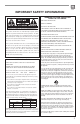
IMPORTANT SAFETY INFORMATION WARNING FOR YOUR PROTECTION READ THE FOLLOWING: KEEP THESE INSTRUCTIONS HEED ALL WARNINGS FOLLOW ALL INSTRUCTIONS The symbols shown above are internationally accepted symbols that warn of potential hazards with electrical products. The lightning flash with arrowpoint in an equilateral triangle means that there are dangerous voltages present within the unit.
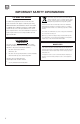
IMPORTANT SAFETY INFORMATION U.K. MAINS PLUG WARNING A molded mains plug that has been cut off from the cord is unsafe. Discard the mains plug at a suitable disposal facility. NEVER UNDER ANY CIRCUMSTANCES SHOULD YOU INSERT A DAMAGED OR CUT MAINS PLUG INTO A 13 AMP POWER SOCKET. Do not use the mains plug without the fuse cover in place. Replacement fuse covers can be obtained from your local retailer. Replacement fuses are 13 amps and MUST be ASTA approved to BS1362.
EC - DECLARATION OF CONFORMITY Brand: Equipment Type: Model names: JBL Commercial Audio Mixer-Amplifiers CSMA 180, CSMA 1120, CSMA 240, CSMA 280, CSMA 2120 We, Harman International, declare under our sole responsibility that the product, to which this declaration relates, is in conformity with the following standards. Report No.
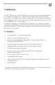
1.0 Welcome The JBL® CSMA series of Mixer-Amplifiers are a professional tool designed and built for Installed sound applications. There are both single channel and two channel models with four or eight mixer channels, respectively. They provide mixer capability with independent level control for each input channel and amplification with a choice of low impedance, 70V or 100V outputs. The product includes a rack mounting kit for installations to a cabinet.
1.2 Front Panel Controls and Indicators Figure 1.2 Front View A B C D E G F A. Input Level Controls B. Input signal presence is indicated by green illumination of the ring around the input level controls C. Output Volume Controls D. Illuminated ring around the output volume control will light green with signal presence while red indicates clipping, i.e. the signal has reached the threshold of audible distortion. E. Power Switch F. Illuminated ring around the power switch.
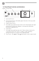
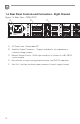
1.3 Rear Panel Controls and Connectors - Four Channel Figure 1.3 Rear View - CSMA 1120 CAUTION - TO REDUCE THE RISK OF ELECTRIC SHOCK, GROUNDING OF THE CENTER PIN OF THE PLUG MUST BE MAINTAINED. MADE IN MALAYSIA CH2-4 IN / AUX OUT 100V 70.
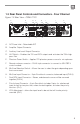
1.4 Rear Panel Controls and Connectors - Eight Channel Figure 1.4 Rear View - CSMA 2120 AUX 1 OUT LINE MIC LINE MIC CH4 INPUT 1 - CH1 TO AMP2 2 - CH2 TO AMP2 3 - CH3 TO AMP2 4 - CH4 TO AMP2 5 - AMP1 Hi-Z 6 - PHANTOM 7 - CH5 TO AMP1 8 - CH6 TO AMP1 9 - CH7 TO AMP1 10 - CH8 TO AMP1 11 - AMP2 Hi-Z 12 - NC CH8 INPUT 1 2 3 4 5 6 7 8 9 10 11 12 C 10 INPUT ROUTING AUX 2 OUT AMP 1 100V 70.
LINE MIC MONO SUM LINE MIC LINE H MONO SUM MIC MONO SUM CH1 INPUT MONO SUM CH2 INPUT CH3 INPUT F F. MIC CH6 INPUT MONO SUM LINE CH7 INPUT MONO SUM G CH5 INPUT I LINE MIC PRIORITY CH 1 VOX LINE MIC CH 5 VOX PRIORITY J Mic/Line Input Connector – 3 pin Euro-block connector for a balanced input source. (Ch 2-4 & 6-8) G. Dual RCA Input Connector – Stereo, unbalanced sources will be summed together. (Ch 2-8) H.
2.0 Setup 2.1 Unpacking Your Amplifier Please unpack and inspect your amplifier for any damage that may have occurred during transit. If damage is found, notify the transportation company immediately. Only you can initiate a claim for shipping damage. We will be happy to help as needed. Save the shipping carton as evidence of damage for the shipper’s inspection. We also recommend that you save all packing materials so you will have them if you ever need to transport the unit.
Figure 2.2.1 Dimensions 43.3 mm [1.7 in] CSMA 180, CSMA 1120 218.44 mm [8.6 in] 303.4 mm [11.9 in] 43.3 mm [1.7 in] CSMA 240, CSMA 280, CSMA 2120 436.88 mm [17.2 in] 303.4 mm [11.9 in] Figure 2.2.
Figure 2.2.3 Rack mounting of two half rack Mixer units. Solution A: Rack Mounting Two Half Rack Mixer Amplifiers To install two half-rack width units in your cabinet system, refer to Figure 2.2.3 and follow the steps below: 1. Align two modules side by side and upside down with the front panel towards the same direction. 2. Connect them with the flat bracket using the screws provided. 3. Attach the front angle brackets to each side of the front of the amplifier assembly using the screws provided. 4.
Figure 2.2.4 Rack Mounting a Half Rack Mixer Amplifier Solution B: Rack Mounting Single Half Rack Mixer Amplifier To install a single half-rack unit, refer to Figure 2.2.4 and follow the steps below: 1. Determine which side of the rack opening will be used for the amplifier and attach the long angle bracket to the other side at the front of the amplifier using the screws provided. 2.
Figure 2.2.5 Rack Mounting Full Rack Mixer Amplifier Solution C: Rack Mounting Full Rack Mixer Amplifier To install a full-rack width unit, refer to Figure 2.2.5 and follow the steps below: 1. Attach the front angle brackets to each side of the front of the amplifier using the screws provided. 2. Attach the rear flat brackets to each side of the rear of the amplifier with the screws provided. 3. Install the unit into the cabinet using the rack mount screws through the front angle brackets.
2.3 Ensuring Proper Cooling When using an equipment rack, keep a minimum space of 4 inches (10cm) from the top surface of the unit. Close any open spaces in the rack with blank panels. DO NOT block any air vents. The side walls of the rack should be a minimum of 2 inches (5 cm) from the amplifier sides. The back of the rack should be open. 2.
2.5 Output Wiring and Connectors To drive distributed speaker systems designed to operate at 70V or 100V, connect to the corresponding output terminals. JBL recommends using pre-built or professionally wired, high-quality, two-conductor, heavy gauge speaker wire. Speakers wires should be twisted cable, if possible. To prevent the possibility of short-circuits, the wires should be stripped back no greater than 6 mm (1/4 inch), see Figure 2.5.2.
Figure 2.6 Wiring Audio System Professional audio system CAUTION - TO REDUCE THE RISK OF ELECTRIC SHOCK, GROUNDING OF THE CENTER PIN OF THE PLUG MUST BE MAINTAINED. MADE IN MALAYSIA CH2-4 IN / AUX OUT 100V 70.7V COM CSR-V ONLY MIC MONO SUM LINE MIC LINE MIC PRIORITY CH1 INPUT Hi-Z PHANTOM LINE LINE MIC CH2 INPUT 5028384 CLASS 2 WIRING CH3 INPUT CSMA 1120 AMP OUT CH4 INPUT 40W AUX OUT 100-240 V~ 50/60Hz MONO SUM VOX MONO SUM CSR-V LEVEL CD /OPTICAL SPK 1 + 2 VIRTUAL 2.
2.7 Connecting to AC Mains Connect your amplifier to the AC mains power source (power outlet) with the supplied AC power cord. First, connect the IEC end of the cord set to the IEC connector on the amplifier; then, plug the other end of the cord set to the AC mains. When properly connected to a live power source, the power ring should illuminate with a green color. WARNING: The third prong of this connector (ground) is an important safety feature.
3.0 Operation 3.1 Precautions Your amplifier is protected from internal and external faults, but you should still take the following precautions for optimum performance and safety: 1. Before use, your amplifier first must be configured for proper operation, including input and output wiring hookup. Improper wiring can result in serious operating difficulties. For information on wiring and configuration, please consult the Setup section of this manual. 2.
3.2 Input Routing INPUT ROUTING 1 2 3 4 5 6 7 8 9 10 11 12 1 - CH1 TO AMP2 2 - CH2 TO AMP2 3 - CH3 TO AMP2 4 - CH4 TO AMP2 5 - AMP1 Hi-Z 6 - PHANTOM 7 - CH5 TO AMP1 8 - CH6 TO AMP1 9 - CH7 TO AMP1 10 - CH8 TO AMP1 11 - AMP2 Hi-Z 12 - NC The two channel models, CSMA240, CSMA280 and CSMA2120 include a default routing of input channels 1-4 to amplifier 1 and input channels 5-8 to amplifier 2. The user may also take any input and have it routed to both outputs by selecting the appropriate switch.
3.6 Priority Muting With CSMA180 and CSMA1120 Input Channel 1 may be used as a priority channel, muting all other channels when pins 4 and 5 are shorted using a switch closure. If the amplifier has entered sleep mode due to inactivity, invoking priority will also bring the unit out of sleep and ready for transmitting an announcement. The CSMA240, CSMA280 and CSMA2120 lets Input Ch1 operate with priority over all inputs into Amp 1.
4.0 Troubleshooting CONDITION: No power to the mixer-amplifier so that the power ring is not illuminated. POSSIBLE REASON: The mixer-amplifier is not plugged into the power receptacle CONDITION: No sound or low sound. POSSIBLE REASON: The input signal is not present or at a very low level. POSSIBLE REASON: The Master Volume control is turned down. POSSIBLE REASON: A CSR-V is connected and turned down. POSSIBLE REASON: Mixer channel inputs are turned down.
Appendix A: Target Performance Specifications Performance Max Output Power per Channel into 4 Ω or 8 Ω; 1kHz, ≤ 0.5% THD CSMA 180 CSMA 1120 CSMA 240 CSMA 280 CSMA 2120 80W 120W 40W 80W 120W Insertion Loss (70V & 100V outputs) 1 dB maximum 10W 15W 5W 10W 15W Number of Input Channels 4 4 8 8 8 Number of Output Channels 1 1 2 2 2 Continuous Power per Channel 5.
Appendix B : Block Diagram Figure C CSMA 2120/280/240 Block Diagram Phantom Power (SW6) Input Gain SPI Line Mic Mic/Line [Bal] CH1 TO AMP1 Gain 1 CH1 ∑ SW1 CH1 VOX CH1 PTT CH1 TO AMP2 CH1 Priority OR Input Gain Line CH2 TO AMP1 SPI Mic Mic/Line [Bal] ∑ Attenuation CH8 TO AMP1 CH2 TO AMP1 Gain 2 CH2 RCA [MONO SUM] CH2 TO AMP2 SW2 CH3 & CH4 Similar to CH2 Input Gain SPI Line Mic Mic/Line [Bal] CH5 TO AMP2 Gain 5 CH5 SW7 CH5 VOX CH5 PTT CH5 TO AMP1 CH5 Priority OR Input Gain
P2 P2 P2 P2 Preamp Line Line Out Out 1 1 Preamp ∑ ∑ SPI 1 SPI 1 Clip 1 Clip 1 Tone Control Tone Control Bass Bass VCA VCA Treble Treble Master 1 1 Master HPF HPF VCA VCA 1 1 Scaling Scaling HPF CNTL(SW5) HPF CNTL(SW5) Limiter Limiter Output Output XFMR XFMR Power Power AMP1 AMP1 COM COM 70.7V 70.
Appendix C: Contact Information For additional information, please consult JBL Professional Customer Service, your system installer or retailer. On The World Wide Web: www.jblcommercialproducts.com Professional Contacts, Outside the USA: Contact the JBL Professional Distributor in your area. A complete list of JBL Professional international distributors is provided at our U.S.A. Website: www.jblpro.
JBL Commercial 8760 South Sandy Pkwy.