
Owner manual


Operation Manual
Macro-Tech MA-3600VZ Power Amplifier
page 10
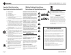
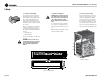
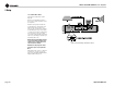
3.6.3 Parallel-Mono Mode
Typical input and output wiring is shown in
Figure 3.8.
INPUTS: Connect input wiring to Channel 1.
Refer to Section 3, Figure 3.4 for input connector
pin assignments.
OUTPUTS: Install a jumper wire between the
positive binding posts of both Channel 1 and
Channel 2 that is at least 14 gauge in size;
Connect positive (+) speaker lead to Channel 1
positive binding post of amp; connect negative
(–) speaker lead to Channel 2 negative binding
post of amp. Refer to Section 3.5 for output
connector pin assignments. Make sure the Mode
switch is set to the “Bridge” position when oper-
ating in Bridge-Mono mode.
NOTE: Turn down (full CCW) the Channel
2 level control when operating in Paral-
lel-Mono mode, as the Channel 1 level
control works both channels.
NOTE: Remove the jumper wire before
changing to any mode except Parallel-
Mono.
NOTE: Crown provides a reference of wiring pin
assignments for commonly used connector
types in the Crown Amplifier Application Guide
available at www.crownaudio.com.
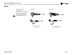
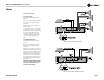
Figure 3.8 System Wiring, Parallel-Mono Mode
3 Setup