
Owner manual


P.I.P.–AMCb
Page 5
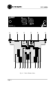
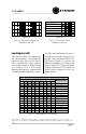
2 Facilities
A. Thumb Screws
Use these thumb screws to fasten the
PIP to the amplifier. A circlip prevents
them from falling out.
B. Auxiliary SIP sockets
The two auxiliary SIP sockets hold
spare crossover SIP resistors. SIPs with
values of 33, 20 and 10 kohm are pro-
vided. Crossover frequencies are cho-
sen using various SIP combinations.
C. XLR Connectors
Balanced 3-pin XLR connectors are
provided for input (female XLR) and
output (male XLR). These connectors
are wired with pin 2 high.
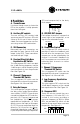
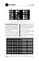
D. Constant-Directivity Horn
Equalization DIP Switch
This nine-segment DIP switch sets both
the +3 dB shelving frequency and the
–3 dB low pass roll-off frequency of the
constant-directivity horn equalization
filter. See Figure 3.6.
E. Channel 2 Compressor
Threshold DIP Switch
This six-segment DIP switch sets the
threshold of the channel 2 compressor.
See Figures 3.8, 3.9a and 3.9b.
F. Daisy Out Jumper
This seven-position jumper configures
the “daisy chain” output. Seven options
are available: (1) PROC LO passes pro-
cessed low frequencies (EQ and com-
pression); (2) LO passes unprocessed
low frequencies; (3) EQ LO passes
equalized low frequencies; (4) THRU
directly passes the input to the output;
(5) EQ HI passes equalized high fre-
quencies; (6) HI passes the unproc-
essed high frequencies; and (7) PROC
HI passes processed high frequencies
1
PIN
2345678
SIP
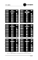
H. Compressor Control
This six-segment DIP switch makes it
possible to select the feedback path
that will drive the compressors. Each
compressor can be controlled by the
channel 1 or channel 2 feedback sig-
nal. The compressors can also be con-
trolled by both channels or neither
channel (off).
I. Channel 1 Compressor
Threshold DIP Switch
This six-segment DIP switch sets the
threshold of the channel 1 compressor.
See Figures 3.8, 3.9a and 3.9b.
J. Low-Frequency Equalization
DIP Switch
This nine-segment DIP switch sets the
+6 dB boost frequency of the vented
box equalization filter. See Figure 3.4.
K. Crossover SIPS
These SIP resistors control the cross-
over frequency. A 20 kohm SIP is in-
stalled at the factory providing a
crossover frequency of 800 Hz. Spare
SIPs are provided (B) which can be
used to set up several other crossover
frequencies. See Figure 3.1.
(EQ and compression) to the daisy
chain output.
PROC LO
LO
EQ LO
EQ HI
HI
PROC HI
THRU
DAISY
OUT
G. CH1/CH2 OUT Jumpers
Each output channel has a jumper that
sends high or low frequencies, or no
signal to the selected channel.
HI
LO
HI
LO
CH2 OUT CH1 OUT