
Owner manual


P.I.P.–AMCb
Page 6
=
R
1
× R
2
R
1
+ R
2
R (ohms)
3 Installation
Before installing any
P.I.P.
in your am-
plifier, turn down the amplifier’s level
controls, turn off the amplifier and
disconnect the AC power. Even
though the amplifier is off, there
could still be enough energy in the
circuitry to cause electric shock.
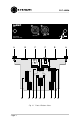
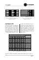
Crossover Selection
The crossover is a fourth-order Link-
witz-Riley type with state-variable to-
pology. Its frequency is set by the
Single Inline Package (SIP) resistors
installed in the SIP1 and SIP2 sock-
ets (see Figure 2.1).
Note: Four equal
value 1% resistors can also be used
in place of each SIP.
The factory set crossover frequency
is 800 Hz. The supplied SIPs can be
installed in combinations for cross-
over frequencies of 500, 800, 1200,
1600, 2000 and 2400 Hz. The extra
SIPs are stored on the circuit board
in two spare sockets (see Figure 2.1).
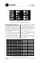
The Crossover Resistor Value Table
(see Figure 3.1) shows resistor val-
ues (R) required to achieve a specific
crossover frequency. Standard SIP
values are used, which are identical
to the required values of single 1%
resistors.
CROSSOVER
R (kohms) Frequency (Hz)
220
150
120
100
68
47
39
33
27
22
20
18
15
12.5 (33+20)
10
8.7
7.7 (33+10)
6.7 (20+10)
5.6
5.1
4.7
3.9
3.3
3.0
2.7
2.2
2.0
72
106
133
159
234
339
408
483
590
723
796
884
1062
1278
1592
1942
2074
2387
2843
3122
3388
4083
4825
5308
5898
7238
7962
(500)
(800)
(1200)
(1600)
(2000)
(2400)
Fig. 3.1 Crossover Resistor
Value Table
equation must be used to calculate R
(resistance) when using both sockets:
*R1= resistor value for socket 1; R2= resistor value for socket 2.
1
Siegfried H. Linkwitz, “Active Crossover-Networks for Noncoincident drivers,” JAES, Jan/Feb, 1976.
To calculate the resistor values for
any crossover frequency, use this
formula:
Crossover
Frequency
=
15,915,000
R
(
ohms
)
(Hz)
*
When a single socket is used, this
equation is concise. But because the
two sockets are in parallel, a special
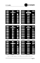
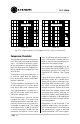
Figures 3.2 and 3.3 show the typical
frequency and phase response of
the crossover when set for 800 Hz
(R=20 kohm). Notice that each side
of the crossover has identical phase
response. This has been shown by
Linkwitz
1
to yield optimum on-axis re-
sponse in a multiple driver system.