P.I.P.-RPA P.I.P.-RPAT © 2002 by Crown Audio, Inc., P.O. Box 1000, Elkhart, IN 46515-1000 U.S.A. Telephone: 574-294-8000. Fax: 574-294-8329. Trademark Notice: PIP is a trademark and Crown and P.I.P. are registered trademarks of Crown International. Other trademarks are the property of their respective owners. Printed on recycled paper.
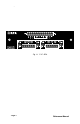
P.I.P.-RPA Fig. 1.1 P.I.P.
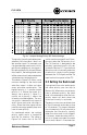
P.I.P.-RPA 1 Welcome Thank you for purchasing the Crown P.I.P.®-RPA accessory. PIP™ modules are designed to install quickly into the rear panel of many Crown amplifiers. PIP stands for “Programmable Input Processor.” Their versatile features expand the capabilities of your amplifier and enable you to customize it for your particular needs. The P.I.P.-RPA adds the features of a remote-controlled 4-input 2-output mixer to the input of your amplifier.
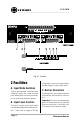
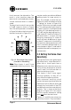
P.I.P.-RPA Fig. 2.1 Facilities 2 Facilities A. Input Mode Switches These gold-plated three-position switches select the mode of each main audio input: mic-level, line-level, or mic-level with phantom power. B. Input Level Controls The level of each main audio input can be adjusted with these level controls. They have a range of 36 dB. Page 4 Using them, you can compensate for a wide range of input signal levels. C.
P.I.P.-RPA Main Audio Inputs There are four balanced main audio inputs. Inputs A and B are normally fed to Ch. 1 of the amplifier. Inputs C and D are normally fed to Ch. 2. Each input remains off (attenuated 84 dB) until a positive DC voltage greater than 5 V is applied to the corresponding remote input (10 V results in no attenuation). Remote Inputs / 10 V Output There is a remote control input for each main audio input and a 10 VDC supply output for feeding them (see Section 3.6).
P.I.P.-RPA 3 Installation This section provides general installation instructions. For additional information on using Crown PIP modules, visit the Crown website at www.crownaudio.com. Normally the mix of Inputs A and B feeds Channel 1 of the amplifier and the mix of Inputs C and D feeds Channel 2. This can be changed by the routing/priority switch when the Tie function is turned on (see Section 3.7). The internal controls of the P.I.P.RPA must be set prior to installation.
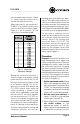
P.I.P.-RPA Fig. 3.4 Sample Routing/Priority DIP Switch Settings The priority of each input determines whether it will override or “duck” under another input. For example, you can feed background music into Input B and a paging mic into Input A. By setting the priority of Input B lower than Input A, the background music will be automatically attenuated when someone uses the paging mic. The table in Figure 3.
P.I.P.-RPA fore it removes the attenuation. The result is a fast transition when the duck circuit is activated and a slower, smooth transition when it is deactivated. The duck level controls have a wide 0–70 dB range as shown in Figure 3.6. (The setting numbers in the table in Figure 3.6 refer to the tick marks on the duck level pot in Figure 3.5.) may be used to provide two different ducking levels for lower priority inputs.
P.I.P.-RPA cal to the duck level controls. Figure 3.7 shows how the control can increase the relative sensitivity. When the control is set to position 1 (0 dB) it is so insensitive the voiceover circuit will almost never trigger. When it is set to position 12, the sensitivity is increased 26 dB. pending upon your particular application. The steps we provide are for a common scenario which shows the principles involved.
P.I.P.-RPA voice-over sensitivity control fully counterclockwise (setting 0) will turn the circuit off. Fig. 3.8 Steps 1 & 2 Input A. 4. If you haven’t yet done so, adjust the duck level per Section 3.2. 5. Turn the voice-over sensitivity control of Input A to its middle setting (setting 6 in Figure 3.5). 6. Turn off the power amplifier and unplug its power cord. Refer to Section 3.4 and install the PIP into the amplifier. Reconnect power to the amplifier and turn it on. 7.
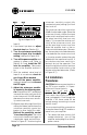
P.I.P.-RPA L BACK PANE ER OF AMPLIFI P.I.P. LE MODU Fig. 3.9 Installation into a Standard PIP Amplifier FROM AM PLIFIER PIP2 ADA PTER B A 18 PIN (B) B 20 PIN (A) A Fig.3.10 PIP2 Input Adapter Connection L BACK PANE OF PIP2 AMPLIFIER TER PIP2 ADAP P.I.P. LE MODU Fig. 3.11 Installation into a PIP2 Amplifier 2. Remove the existing PIP module or panel (two screws). For PIP2 amplifiers, this may involve disconnecting the PIP from a PIP2 input adapter (see Figures 3.10 and 3.11).
P.I.P.-RPA Figure 3.12 shows how to wire a balanced and unbalanced source or daisy-chain output to the barrier block connectors. near the output cables or noise and/ or feedback oscillation may occur. It is wise to take similar precautions with line-level input cables too. Important: If the amplifier is used in either Bridged-Mono or Parallel-Mono mode, you must turn the Ch. 2 amplifier level control off (fully counterclockwise). The input and level control of Ch.
P.I.P.-RPA the signal ground is isolated from the chassis ground by a 82-ohm resistor and 0.1-microfarad capacitor as shown below: switch to maximum attenuation. A 10-V source is provided on the PIP module for your convenience, but an external source can also be used. A 10-Kohm, C-taper audio pot is suggested for remote lines (see Appendix A-1). Crown’s RPA-RMT is ideal. Linear pots will work, but are less precise at higher output levels.
P.I.P.-RPA Note: The 10 V output can also be wired directly to the remote inputs to turn them on with no attenuation. Fig. 3.16 Remote Control & Tie Function Wiring If variable controls aren’t required, the 10-V output can be connected directly to the remote control input for no attenuation, or a resistor can be used for a fixed attenuation level. The table in Figure 3.15 shows how much attenuation is achieved with different remote-control resistance values. The corresponding voltage is also provided.
P.I.P.-RPA 3.8 Using the Audio Bus The audio bus inputs and outputs are provided so additional signals can be added to the mixed bus (input) of each channel or the mixed (output) signals can be fed to other components or amplifiers (see Section A.4 in the Appendix). As such they are very similar to the “Aux Return” and “Aux Send” connections on a typical mixer. One common use for the audio bus inputs is to “stack” multiple P.I.P-RPAs.
P.I.P.-RPA Frequency Response: ±0.5 dB from 30 Hz to 15 kHz without isolation transformers. ±0.5 dB from 50 Hz to 15 kHz with isolation transformers. Harmonic Distortion (THD): Less than 0.1% THD from 20 Hz to 20 kHz. Less than 0.5% THD from 30 Hz to 15 kHz at +10 dB. Common Mode Rejection: Better than 50 dB from 20 Hz to 10 kHz. Better than 45 dB from 10 to 20 kHz. P.I.P.-RPA(T) better than 40 dB from 10 to 20 kHz. vate an attenuation (duck) circuit to override other inputs.
P.I.P.-RPA 10 V Output A 10 VDC ± 50 mV current-limited output is provided for use with the remote control inputs and the Tie input. It has a 75-ohm output impedance. Audio Bus Audio Bus Inputs: One independent unbalanced current summing input for each output channel of the Reference Manual PIP There is unity gain into either input when a 10 K ohm source resistor is used.
P.I.P.-RPA Fig. 3.
P.I.P.-RPA Appendix A.1 Custom Remote Control Important: This Appendix includes instructions on how to modify the P.I.P.–RPA to accommodate special needs. Only a competent technician should attempt to make these modifications. Other than the ones described here, no other modifications are approved by Crown. If you have any questions or need further technical assistance, please contact the Crown Technical Support Group at 800-342-6939, or contact your local representative.
P.I.P.-RPA Pots other than 10 K ohm will work best if you change the scaling resistors to match the pot value. For example, use a 20 K resistor for a 20 K pot. Do not exceed 50 K. The scaling resistor locations are shown in Figure A.1. Resistor R65 is used for Input A, R74 for Input B, R79 for Input C, and R89 for Input D. Remove the front panel (4 screws) from the top and bottom circuit boards to access the scaling resistors.
P.I.P.-RPA The table in Figure A.4 shows the resistor value to use for different maximum attenuation values. Note: The values in Figure A.4 are for use with a 10 K remote control pot only. If a different value pot is used, the following equation will solve for the correct resistor value: “RL” is the value of the limit resistor in kilohms. “VL” is the minimum desired remote control voltage in volts. It can be found by selecting the maximum desired attenuation from either Figure A.4 or 3.