
Owner manual


Page 5
Reference Manual
P.I.P.-RPA
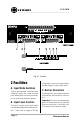
Main Audio Inputs
There are four balanced main audio
inputs. Inputs A and B are normally
fed to Ch. 1 of the amplifier. Inputs C
and D are normally fed to Ch. 2. Each
input remains off (attenuated 84 dB)
until a positive DC voltage greater
than 5 V is applied to the corre-
sponding remote input (10 V results
in no attenuation).
Remote Inputs / 10 V Output
There is a remote control input for
each main audio input and a 10 VDC
supply output for feeding them (see
Section 3.6). Each main audio input is
normally off (attenuated 84 dB) until a
positive DC voltage greater than 5 V is
connected to the corresponding re-
mote input. If the 10 V supply is
strapped directly to a remote input,
the main audio input will have no
attenuation.
Audio Bus Input / Output
There is also an unbalanced audio
bus input and output for each chan-
nel. Each bus input and output pair
shares a common ground connec-
tion. The bus outputs contain the
mixed audio signals from Inputs A–D
which feed the corresponding ampli-
fier channel.
Note: The audio bus outputs are
inverted. The mating bus inputs cor-
rect this by again inverting the sig-
nal.
Tie Input
Finally there is a “Tie” input which is
a logic input and can be switched on
by feeding a positive DC voltage to it.
It enables the audio inputs and voice-
over priorities of Ch. 1 to be “tied” to
Ch. 2 and vice versa.
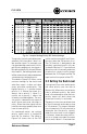
D. Routing/Priority Switch
This 8-segment DIP (dual in-line
package) switch is comprised of eight
individual switches. Flipping them
down toward the bottom circuit board
turns them off. Flipping them up to-
ward the top circuit board turns them
on. The DIP switch is used to pro-
gram the routing and priority of each
main audio input. See Section 3.1.
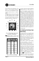
E. Duck Level Controls
The “duck level” is the amount of
attenuation applied to a lower priority
input when a higher priority input is
activated. The first control (closest to
the front panel of the PIP) sets the
duck level triggered by Input A and
the third control sets the duck level
triggered by Input C. The attenuation
range is 0 to 70 dB.
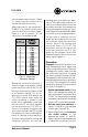
F. Voice-Over Sensitivity
Controls
The “voice-over sensitivity” is the level
required from an input signal before
the “duck” circuit is activated, caus-
ing lower-priority inputs to duck to a
preset attenuation level. The second
control (closest to the front panel)
sets the sensitivity of Input A and the
fourth control sets the sensitivity of
Input C. The voice-over sensitivity
controls have a range of 26 dB.