
Owner manual


Page 6
Reference Manual
P.I.P.-RPA
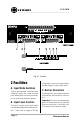
3 Installation
This section provides general instal-
lation instructions. For additional in-
formation on using Crown PIP mod-
ules, visit the Crown website at
www.crownaudio.com.
The internal controls of the P.I.P.-
RPA must be set prior to installation.
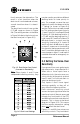
Note: An accessory, a PIP extender
card (P.I.P.-EXT), is available if you
prefer to make the voice-over and
duck level adjustments while the PIP
is operating. This allows you to test
your settings and easily make
changes while you fine-tune the in-
stallation.
3.1 Setting the
InputRouting/Priority
Switch
The routing/priority switch serves two
purposes. First, it works together with
the Tie function to control audio sig-
nal routing. Second, it sets the prior-
ity of Inputs B, C and D (Input A
always has the highest priority. Input
C always has the second highest
priority.)
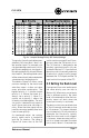
The routing/priority switch is the 8-
segment DIP switch shown in Fig-
ures 2.1 and 3.2. Notice that it is
mounted upside-down to the under-
side (component side) of the top
circuit board.
Normally the mix of Inputs A and B feeds
Channel 1 of the amplifier and the mix of
Inputs C and D feeds Channel 2. This
can be changed by the routing/priority
switch when the Tie function is turned on
(see Section 3.7).
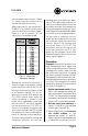
When the Tie function is on, the audio
from Input A is automatically fed to
both Channels 1 and 2. The audio
from the remaining inputs can also
be tied to both channels using the
routing/priority switch. The first three
switch sections control the routing of
Inputs B–D as shown in Figure 3.3.
Fig. 3.2 Priority/Routing DIP Switch
(Inverted for Readability)
Fig. 3.3 Routing/Priority DIP
Switch Functions
Fig. 3.1 P.I.P.-EXT Accessory