
Owner manual


Page 7
Reference Manual
P.I.P.-RPA
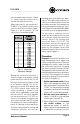
The priority of each input determines
whether it will override or “duck” un-
der another input. For example, you
can feed background music into In-
put B and a paging mic into Input A.
By setting the priority of Input B lower
than Input A, the background music
will be automatically attenuated when
someone uses the paging mic.
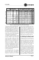
The table in Figure 3.4 shows some
common settings for the switch and
what they mean—it does not show
every possible combination. The
highest priority is 1 and the lowest
priority is 3. Notice that Input A is
always set to priority 1. Input C is
usually set to priority 1 unless the
channels are tied together. The rea-
son for this is because only Inputs A
and C have voice-over sensing cir-
cuitry. Since the other inputs do not
have this sensing capability they must
have a lower priority.
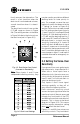
As mentioned earlier, the routing/
priority switch works in conjuction
with the Tie function. The table in
Figure 3.3 shows that all the DIP
switch sections except 5 and 7 func-
tion only when the Tie function is on.
The Tie function is designed to be
remotely controlled and is fully de-
scribed in Section 3.7. If you have no
desire to control it remotely and want
to leave it on, simply install a jumper
between the 10-V output and the Tie
input on the front panel of the PIP
3.2 Setting the Duck Level
If you gave all four main audio inputs
the same priority you can skip to
Section 3.4. When two or more inputs
have a different priority, the duck
level is the attenuation level the low-
priority inputs will duck when the
voice-over circuitry is activated.
The duck circuits have an attack time
of 15 milliseconds and a decay time
of 1.5 seconds. This means the duck
circuit needs only 15 milliseconds to
attenuate the low-priority input(s)
when the voice-over circuit triggers
it. However, when the voice-over cir-
cuit is no longer activated, the duck
circuit waits about 1.5 seconds be-
Fig. 3.4 Sample Routing/Priority DIP Switch Settings