DSC Series Manual ! Installation, Operation, Maintenance and Parts WARNING ! Improper installation, adjustment, alteration, service or maintenance can cause property damage, injury or death. Read and understand the installation, operating and maintenance instructions thoroughly before installing or servicing this equipment. This heater must be installed and serviced by trained gas installation and service personnel only. Inspect the heater annually.
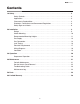
DSC Series Contents 1.0 Safety . . . . . . . . . . . . . . . . . . . . . . . . . . . . . . . . . . . . . . . . . . . . . . . . . . . . . . . . . . . . . . . . . . . . 3 Safety Symbols . . . . . . . . . . . . . . . . . . . . . . . . . . . . . . . . . . . . . . . . . . . . . . . . . . . . . . . 3 Applications . . . . . . . . . . . . . . . . . . . . . . . . . . . . . . . . . . . . . . . . . . . . . . . . . . . . . . . . . . 3 Clearance to Combustibles . . . . . . . . . . . . . . . . . . . . . .
DSC Series 1.0 Safety • Safety Symbols • Applications 1.0 Safety ! ! WARNING Improper installation, adjustment, alteration, service or maintenance can cause property damage, serious injury or death. Read and understand the installation, operating and maintenance instructions thoroughly before installing or servicing this equipment. Only trained, qualified gas installation and service personnel may install or service this equipment.
DSC Series 1.0 Safety • Clearance to Combustibles Clearance to Combustibles WARNING ! Placement of explosive objects, flammable objects, liquids and vapors close to the heater may result in explosion, fire, property damage, serious injury or death. Do not store, or use, explosive objects, liquids and vapor in the vicinity of the heater. Failure to comply with the published clearances to combustibles could result in personal injury, death and/ or property damage.
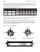
DSC Series 1.0 Safety • Clearance to Combustibles When installing the infrared heater system, the minimum clearances to combustibles must be maintained. These distances are shown in Chart 1.1 and on the heater. If you are unsure of the potential hazards, consult your local fire marshal, fire insurance carrier or other qualified authorities on the installation of gas fired infrared heaters for approval of the proposed installation. Chart 1.1 • Clearance to Combustibles in Inches (see Figure 1.1) Model No.
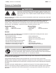
1.0 Safety • Standards, Certifications and Government Regulations DSC Series Standards, Certifications and Governmental Regulations The installation of this heater must comply with all applicable local, state and national specifications, regulations and building codes (contact the local building inspector and/or fire marshal for guidance) before installing the heater system. In the absence of local codes, the installation must conform to the latest edition of the National Fuel Code ANSI Z223.1 (NFPA 54).
DSC Series 1.0 Safety • Standards, Certifications and Government Regulations Electrical: The heater, when installed, must be electrically grounded in accordance with the National Electrical Code ANSI/NFPA 70 (latest edition). Under no circumstances is the electrical supply line to provide any assistance in the suspension of the heater. Ventilation: This heater must be installed in accordance with the requirements set forth in this manual and with the NFPA 54/ANSI Z223.
DSC Series 1.0 Safety • Safety Signs and Labels Safety Signs and Labels It is important to provide warnings to alert individuals to potential hazards and safety actions. ANSI Z83.26/CSA 2.37 requires you to post a sign specifying the maximum permissible stacking height to maintain the required clearances from the heater to the combustibles near the heaters thermostat or in absence of such thermostats in a conspicuous location. Safety warning labels must be maintained on the infrared heater.
DSC Series 2.0 Installation • Design 2.0 Installation WARNING ! Read and understand, the installation, operating and maintenance instructions thoroughly before installing or servicing this equipment. Only trained, qualified gas installation and service personnel may install or service this equipment. Design Crown Verity Inc. Patio Heaters are designed specifically for comfort heating in an outdoor environment.
DSC Series 2.0 Installation • Heater Mounting • Optional Mounting Kit Heater Mounting ! WARNING Improper suspension of the infrared heater may result in collapse and persons being crushed. Always suspend from a permanent part of the building structure that can support the total force and weight of the heater. Failure to maintain minimum clearance to combustibles may result in fire and/or explosion, property damage, serious injury or death.
DSC Series 2.0 Installation • Heater Mounting • Recommended Mounting Heights Recommended Mounting Heights ! WARNING Heater must be installed at least 6.5 feet above the finished floor. Chart 2.1 • Recommended Mounting Heights BTU/h Recommended Mounting Height Approximate Coverage Area Approx. Coverage (sq. ft.) 31,000 8’-0” to 12’-0” 8’ x 8’ 64 sq. ft. 34,000 8’-6” to 13’-0” 9’ x 9’ 81 sq. ft. NOTE: This chart is provided as a guideline. Actual conditions dictate variances from this data.
DSC Series 2.0 Installation • Heater Mounting Figure 2.3 shows different types of mounting configurations. Depending on the type of mounting you use, be sure to: 1 2 3 4 Prepare mounting surface. If necessary, weld blocks to mounting structure, drill holes, etc. Fasten beam clamp, screw hook or other type of suspension anchor to hanging point. Attach threaded rod and turnbuckle to anchor. Check that it is securely attached. Attach heater to turnbuckle.
DSC Series 2.0 Installation • Gas Supply Gas Supply The gas supply to the infrared patio heater must be connected and tested in accordance with national, state, provincial, and local codes along with the guidelines in the manual. In the United States refer to the latest edition of the ANSI Z223.1 (NFPA 54) standard; and in Canada, refer to the latest edition of the CAN/ CGA B149.1 Standard.
DSC Series 2.0 Installation • Gas Supply • Gas Connection When connecting gas piping to the unit, the use of a thread joint compound is required. The thread compound (pipe dope) shall be resistant to the action of liquefied petroleum gas or any other chemical constituents of the gas to be conducted through the piping. Use of Teflon® tape is not permitted.
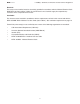
DSC Series 2.0 Installation • Gas Supply • Gas Connection Figure 2.4 • Gas Connection - End View (shown installed from above) NOTE: Do not exceed 14 inches W.C. to the appliance. Use a regulator when gas supply pressure exceeds 14 inches W.C. Shut off valve / inlet tap (field supplied) Tee Elbow Ground joint union Drip leg / Sediment trap (field supplied) Figure 2.
DSC Series 2.0 Installation • Gas Supply • Leak Testing ! Leak Testing Use a soap solution or equivalent for leak testing. Leak testing solution must be non-corrosive, and be rinsed off immediately after the leak test. Never test for leaks with an open flame. Failure to comply could result in personal injury, property damage or death. Always leak test the final gas assembly for gas leaks according to the procedures outlined in NFPA 54 and all local codes/or standards.
DSC Series 2.0 Installation • Electrical Requirements Electrical Requirements ! WARNING Incorrect or improper wiring may result in shock, injury or death. Field wiring to the heater must be connected and grounded in accordance with national, state, provincial, local codes and to the guidelines in this manual. Refer to the most current revisions to the ANSI/NFPA 70 Standard.
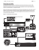
DSC Series 3.0 Maintenance • Wiring Diagrams Figure 2.7 • Internal Wiring Diagram SENSE GROUND VALVE THERMOSTAT SENSE VALVE + IGNITION MODULE GROUND VALVE THERMOSTAT VALVE + SPARK SPARK IGNITION MODULE SPARK SPARK Figure 2.8 • Field Wiring Diagram Starting Amp Draw: 0.65 Amp Running Amp Draw: 0.
DSC Series 2.0 Installation • Ventilation Ventilation ! WARNING Improper or insufficient ventilation may result in explosion, fire, health problems, carbon monoxide poisoning or death. Vent enclosed spaces and buildings according to national, state, provincial and local codes. This infrared heater must be vented in accordance with national, state, provincial and local codes and the guidelines in this manual. Refer to the latest edition of the ANSI Z223.1 (NFPA 54) Standard.
DSC Series 3.0 Operation • Sequence of Operation 3.0 Operation ! WARNING Improper operation of the heater may result in explosion, fire, shock and carbon monoxide poisoning. Follow all guidelines and warnings in this manual and national, state, provincial and local codes. Always conduct safety checks before operating the heater. Do not operate the heater in unsafe conditions. Important! Before operating the heater, conduct the following safety procedures: • Check for any possible gas leaks.
DSC Series 4.0 Maintenance 4.0 Maintenance ! WARNING Always wear clothing that protects the body and use protective glasses when servicing the heater. Electrical shock or explosion may occur when conducting maintenance while the heater is connected to the power source and gas supply. Disconnect power and gas supply to heater before servicing. Burner malfunction may result in explosion or fire. Never operate the heater if there are any signs of malfunction, excessive wear or damage.
DSC Series 4.0 Maintenance • Service Access Panel Removal Service Access Panel Removal Before removing the service access panel on appliance, allow the unit to cool completely before servicing. To remove the service access panel a ¼” nut driver will be needed. 1 Remove the two ¼” screws on the control end of the unit first while holding the panel in place (see Figure 4.1). 2 Proceed to the opposite side of the unit while holding the panel in place and remove the last two ¼” screws.
DSC Series 4.0 Maintenance • Troubleshooting Guide Chart 4.1 • Troubleshooting Guide Symptom Possible Cause Corrective Action Burning of gas-air mixture inside plenum (flashback). Rumbling noise present. • Heater mounted at incorrect angle. • Excessive drafts. • Gas leaking at orifice. • Separation of ceramic grids. • Ceramic grids cracked. • Mount at a 0˚- 30˚angle from horizontal. • Relocate heater or shield from draft. • Check with leak detector solution. • Replace burner. • Replace burner.
DSC Series 4.
DSC Series 4.
DSC Series 5.0 Parts • Heater Components 5.0 Parts Figure 5.
DSC Series 5.0 Parts • Parts List Chart 5.1 • Parts List Part No. Description PH-1101 Exterior Casing PH-1104 Control End Panel - A PH-1105 Service Access Panel PH-1106 End Panel PH-1110 Rain Guard PH-1111 Egg Crate PH-1112 Egg Crate Locator PH-1113 Egg Crate Access Bracket PH-1117 Reflector PH-1120 Venturi Gasket Holder PH-1121 Venturi Gasket PH-1122 Insulation PH-1123 5/16”-18x3/4” S.S.
DSC Series 6.0 Limited Warranty 6.0 Limited Warranty One-Year Limited Warranty. Patio Heaters covered in this manual, are warranted by Crown Verity Inc. to the original user against defects in workmanship or materials under normal use for one year after date of purchase. Any part which is determined to be defective in material or workmanship and returned to an authorized service location, as Crown Verity Inc.