
Instruction Manual


4
55
DSC Series
1.0 Safety • Clearance to Combustibles
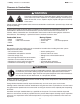
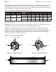
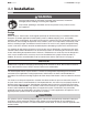
Chart 1.1 • Clearance to Combustibles in Inches (see Figure 1.1)
Figure 1.1 • Clearance to Combustibles
* Heaters mounted on an angle between 1° to 30° must maintain clearances posted for 0° or 30°;
whichever is greater.
Important! If the heater is mounted beneath a non-combustible surface an 8 in. minimum top clearance
must be maintained from the top of the heater to prevent overheating the controls.
Clearance to combustible distances represent a surface temperature of 90°F (32°C) above ambient
temperature. Ensure that building materials with a low heat tolerance (i.e, awnings, fabrics, plastics,
sprinklers, insulation) are protected against degradation. This may require the heater to be mounted at a
distance in excess of the published clearances to combustibles. Contact the factory or the building
material manufacturer for additional information.
SIDE VIEW
End End
Below
Side
Side
END VIEW - 0° MOUNTING ANGLE
Top (to ceiling)
Back
Top
(to ceiling)
Front
END VIEW - 30° MOUNTING ANGLE
Below
30˚
When installing the infrared heater system, the minimum clearances to combustibles must be maintained.
These distances are shown in Chart 1.1 and on the heater. If you are unsure of the potential hazards,
consult your local fire marshal, fire insurance carrier or other qualified authorities on the installation of gas
fired infrared heaters for approval of the proposed installation.
Model No. BTU/h Voltage
Mounting
Angle* Sides Back Top Below Ends Front
DSC-31 31,000 24 VAC
0° 18 N/A 13 48 12 N/A
30° N/A 18 18 40 12 36
DSC-34 34,000 24 VAC
0° 18 N/A 13 48 12 N/A
30° N/A 18 18 40 12 36