
Datasheet


Interface Connectors
The SATA signal segment interface cable has four conductors and three ground connec-
tions. As shown in Package Dimensions, the cable includes a 7-pin signal segment and a
9-pin power segment arranged in a single row with a 1.27mm (0.050in) pitch.
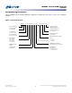
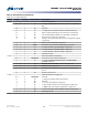
Figure 3: SSD Interface Connections
Power
Segment
Signal
Segment
S1
P1
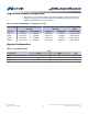
Table 3: SATA Signal Segment Pin Assignments
Signal Name Type Description
S1 GND Ground
S2 A
Differential signal pair A and A#
S3 A#
S4 GND Ground
S5 B#
Differential signal pair B and B#
S6 B
S7 GND Ground
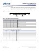
Table 4: 1.8-Inch SATA Power Segment Pin Assignments
Pin# Signal Name Description
P1 V33 3.3V power
P2 V33 3.3V power
P3 GND Ground
P4 GND Ground
P5 V5 No connect
P6 V5 No connect
P7 Reserved No connect
Key Key Key
P8 Optional No connect
P9 Optional No connect
M500DC 1.8-Inch NAND Flash SSD
Interface Connectors
PDF: 09005aef854f62f9
M500DC_1_8_disti.pdf - Rev. D 4/14 EN
5
Micron Technology, Inc. reserves the right to change products or specifications without notice.
© 2013 Micron Technology, Inc. All rights reserved.