
User Guide


MNX10015 / Rev B
4/11/2008 9
5. Identification of inputs:
Mark the Measurement Location Card with a description of each SENSOR
location.
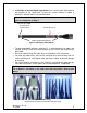
Repeat these steps until all cables have been wired into their respective Channel
Location on the terminal strips.
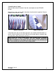
If Cord Grips are used, ensure cord grip covers are securely fastened to base. A
wrench may be needed to ensure the bushing in the cord grip has created a tight
seal around the cable entering the enclosure.
Note: If using the remote output option (with optional plug in connector
#JB905-2A) only (+) and (-) terminals are used. Populate appropriate
number of channels for the plug(s) and slide into place. The enclosure will
have to be modified to account for the exiting cables.
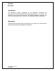
Figure 10. Connecting
Cables to Enclosure
Figure 11. Connecting
Cables to Enclosure