
User Guide


MNX10015 / Rev B
4/11/2008 6
4. Installation of Sensor/Signal Input Cable: Run sensor/signal input cable to
the location of the switch box. Ensure the correct amount of cable is
allocated. Splicing cable is not recommended.
Note: For conduit installations, conduit would be run to the switch box
prior to completion of Step 4.
• To help keep cable locations organized, it is recommended that cables are
marked on BOTH ends and exact locations of the sensors are matched with
their cable.
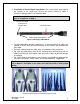
• Run each cable through the cable entry at the bottom of the switch box.
• For cord grip cable entry, take off the cord grip cover with bushing and run
cable into enclosure, hand tighten cord grip cover to base to prevent damage
of cord grip.
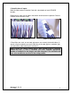
• For 16-32 channel switch boxes, wire tie bases are provided to help manage
the cable into the box, secure cables for the top two boards, if applicable.
Tip: Run rows of cable on same row as on the board, for example, channels
1-6 on Board 1 should be on the outer most left hand side to allow proper
wiring.
Figure 7. Cable Entry
(Representative Photo for Illustration Purposes only)
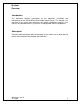
Figure 6. Identifying Cable Marks
CTC Cable Label
BLUNT CUT END
(Connected in
Junction Box
)
Cable Identification Markers