
User Guide


MNX10015 / Rev B
4/11/2008 7
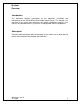
For SB142 and SB242 Series, attach sensor/signal input cables as follows:
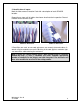
a. Strip outer jacket of cable back 1 ¼”-1 1/2” and remove all of the
shielding.
b. Strip red, black, and (white) insulation back ¼”.
c. Remove each terminal plug from respective channel.
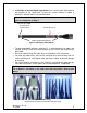
Orientation is as follows: (see Figure 9)
• Red (White in 4-20mA applications) insulated conductor wire is
connected to socket (A).
• Black insulated conductor wire is connected to socket (B).
• White (Red in 4-20mA applications) insulated conductor wire is
connected to socket (C).
• Shield/Drain wire is connected to ground socket (GND).
• Depress selected position button to open terminal for respective wire.
(Small flat blade screwdriver is recommended).
Note: (4) position (and optional 12 position) plug can only be inserted one
way to ensure proper wiring.
Installation considerations for Dual Output Switchbox:
There are several options for consideration of installation of a Dual Output
Switchbox. (Figure 9)
Input signal options are:
• Temperature and Dynamic Acceleration
• Dual Vibration with 4-20mA Output and Dynamic output
Figure 8. Bottom View for Cord Grip Installations