Model NCB-AY Network Combiner Module for Asynchronous Serial Channels Wide Area Router for LONW ORKS® Networks User Guide # S2-60725-310 68-11310-310
CTI Products, Inc. NCB-AY User Guide Standard Limited Hardware Warranty LIMITED WARRANTY. Equipment manufactured by CTI Products, Inc. is warranted to be free from defects in material and workmanship for a period of ONE (1) YEAR from date of shipment to original purchaser. Under this warranty, our obligation is limited to repairing or replacing any equipment proved to be defective by our inspection within one year of sale to the original purchaser.
CTI Products, Inc. NCB-AY User Guide This manual covers NCB units of Revision 300 or higher and NCB/Plug software revision 1.00 or higher. The NCB Unit Revision can be found on the rear of the unit following the letter “U”. The NCB/Plug software revision can be found on the Help/About screen of the program. If the revision of the product in hand is greater than that shown above, there may be additional features supported by the product that are not covered in this manual.
CTI Products, Inc. NCB-AY User Guide Radio Frequency Emissions and Immunity This equipment generates, uses, and can radiate radio frequency energy and, if not installed and used in accordance with the instruction manual, may cause harmful interference to radio communications. Operation of this equipment in a residential area is likely to cause harmful interference in which case the user will be required to correct the interference at his own expense.
CTI Products, Inc. NCB-AY User Guide TABLE OF CONTENTS QUICK-START GUIDE .............................................................................................................................................1 1. INTRODUCTION ...................................................................................................................................................3 WHAT IS AN NCB/AY UNIT? .........................................................................................................
CTI Products, Inc.
CTI Products, Inc. NCB-AY User Guide QUICK-START GUIDE This Quick Start Guide provides a concise series of steps to get a pair of the NCB modules “up and running” quickly so that initial operation may be confirmed. It is highly recommended that, if possible, the pair of NCB/AY modules be tested in your application by first connecting them “back-to-back” with a simple serial “null-modem” cable.
CTI Products, Inc.
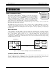
CTI Products, Inc. NCB-AY User Guide 1. INTRODUCTION WHAT IS AN NCB/AY UNIT? Read this section to learn the general function and capabilities of an NCB Router The Network Combiner NCB/AYTM Module is a wide-area router with two asynchronous serial ports that is used for LONW ORKS networks. The NCB/AY unit is used in pairs to connect LONW ORKS networks real-time, spanning distances from building-wide to worldwide..
CTI Products, Inc. NCB-AY User Guide NCB units are available with an option for LonWorks network transceiver type. The ordering code on the rear of the NCB lists the installed options. This ordering code is of the form: NCB/AY-Txxx, where ‘T’ indicates the transceiver type.
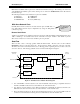
CTI Products, Inc. NCB-AY User Guide Router Function The router contained in each NCB module may be configured as a repeater, bridge, or configured router. The easiest configuration is as a repeater, where all messages which enter the NCB module (via any of the three data sources described above) are simply passed to the other two sources, regardless of the domain, subnet/node, or group destination address. A bridge only passes messages that match one of the two domain IDs configured on the router.
CTI Products, Inc.
CTI Products, Inc. NCB-AY User Guide REAR PANEL BAUD 1 and BAUD 2 Switches Baud rate selection for Port 1 and Port 2. See Section 2, Step 2 for more detail.
CTI Products, Inc. 1.
CTI Products, Inc. NCB-AY User Guide 2. SETUP AND OPERATION STEP 1. MOUNTING Follow the steps in this section to setup an NCB Router for the first time Non-slip rubber feet are included on all NCB modules to allow them to conveniently rest on any horizontal surface. Four 6-32 threaded holes are also available on the bottom of the module to allow bolting of the module in any convenient orientation. WARNING: Care should be taken to limit protrusion of the screw into the module to no more than 0.
CTI Products, Inc. NCB-AY User Guide If OPTION A Switch 5 is DOWN, dynamic determination of the domain/subnet/node number by a Network Management Tool is allowed. OPTION B Switches OPTION B switches set the Serial Port Handshaking options. ON 1 2 3 4 DOWN 1. PORT 1 CTS sense..........................Disabled 2. PORT 1 DSR sense .........................Disabled 3. PORT 2 CTS sense..........................Disabled 4. PORT 2 DSR sense .........................
CTI Products, Inc. NCB-AY User Guide NOTE: Set the “BAUDn” switch to 0 if the respective port will not be used. This is important, as the front panel “ERR” LED will flash continuously if a serial port “BAUD” switch is non-zero and no modem is connected. Mode Switches “MODE 1” and “MODE 2” switches allow setting the NCB for compatibility with certain types of external modems (i.e. dial-up or leased-line). A different type of modem can be connected to each port.
CTI Products, Inc. NCB-AY User Guide NOTE: Set the BAUD 1, BAUD 2, MODE 1, MODE 2, and OPTION B switches according to information in section “2. SETUP AND OPERATION”, “STEP 2. SWITCH SETUP” BEFORE powering up the NCB module. DC Power Connection DC IN DC power must be attached to the NCB module via the DC IN connector (see “APPENDIX C. CONNECTOR DETAILS”). Apply DC power to the NCB module only after all other connections have been made.
CTI Products, Inc. NCB-AY User Guide channel will be connected to Side B of the router shape, and a CUSTOM (WAN) Channel will be connected to Side A of the router shape. Commissioning the NCB control neuron requires that the .XIF file be available. The simplest way to do this is to install the NCB/Plug Configuration Plug-In, as this process copies the required .XIF file to the proper directory.
CTI Products, Inc. NCB-AY User Guide C) Add the Control Neuron Processor to the network drawing: Drag the Device shape to the drawing. The “New Device Wizard” window will be displayed. Specify the desired Device Name. Click NEXT to continue. In the “External Interface Definition” section, choose ‘Existing Template’, click the down arrow and choose the appropriate template as follows: NCBTLC30.XIF should be used for the Control Neuron Processor of an NCB of Version 3, NCBTLC20.
CTI Products, Inc. NCB-AY User Guide STEP 5. CONTROLLING THE WAN CONNECTION At this point, the “local” NCB (the one connected to the LonMaker for Windows NSI) has been configured and fully commissioned for use. This last step involves making a connection to the “remote” NCB via the WAN channel. Normally when using the NCB-AY, since the dedicated channel will allow immediate communication with the remote NCB, no control of the WAN connection is required.
CTI Products, Inc.
CTI Products, Inc. NCB-AY User Guide 3. NETWORK VARIABLE (NV) CONTROL TYPICAL NV BINDINGS This Section contains details of Network Variables and Bindings All commands sent to the NCB module are carried on the LonTalk network in the form of Network Variables bound to the Control Neuron processor inside the NCB module (connected to Side A of the internal router). This section details the Functional Blocks (objects) and the network variables of each.
CTI Products, Inc. NCB-AY User Guide The example in Figure 7 uses multiple Directory Objects with multiple Modem Controller Objects.
CTI Products, Inc. NCB-AY User Guide Dial String (Input) C Language Syntax network input SNVT_str_asc nviDialStr1; network input SNVT_str_asc nviDialStr2; Usage A non-null string sent to this input network variable while the current modem connection state is TEL_NOTINUSE causes the modem to go off hook, wait for a dial tone, then perform a dialing sequence using the provided character string.
CTI Products, Inc. NCB-AY User Guide Connect Status (Output) C Language Syntax network output SNVT_telcom nvoCnctStat1; network output SNVT_telcom nvoCnctStat2; Usage This output network variable provides the current state of the modem connection process.
CTI Products, Inc. NCB-AY User Guide Request Dial String (Output) C Language Syntax network output SNVT_char_ascii nvoReqDialStr1; network output SNVT_char_ascii nvoReqDialStr2; Usage This output network variable is associated with Perpetual Dial-Up Mode (see Tutorial “Which Modem Mode Should Be Used” in section “2. SETUP AND OPERATION”) and is used when the Directory Object storing the telephone number (to be dialed) belongs to a node other than the call-originating NCB.
CTI Products, Inc. NCB-AY User Guide Phone Book Object Modem Controller Object nvoReqDialStr nviReqDialStr nvoDialStr nviDialStr Figure 8 Perpetual Dial-up Mode using NV Bindings 3.
CTI Products, Inc. NCB-AY User Guide Configuration Properties Will Configuration Properties be modified? If NO, and the NCB objects (functional blocks) will be used with factory default settings (Manual Dial-Up or Leased-Line modes, Auto Answer mode Enabled, Ring Mode disabled), skip to Directory Object, later in this section. If YES, but the NCB/Plug plug-in will be used to modify the Configuration Properties, skip to Directory Object, later in this sections and also section “4. ”.
CTI Products, Inc. NCB-AY User Guide Dial Mode C Language Syntax Typedef struct UCPT_DialMode { unsigned char Mode; unsigned char Index; } network input config SCPTdialMode UCPT_DialMode1; network input config SCPTdialMode UCPT_DialMode2; Usage This input configuration network variable allows the modem dialing Mode (Manual or Perpetual) to be set, as well as the Directory entry Index number (0 through 15) that should be used when dialing in Perpetual mode.
CTI Products, Inc. Value Off On NCB-AY User Guide Auto Answer Mode Disabled Enabled Default State On (Enabled) TELEPHONE DIRECTORY OBJECT A Directory Object is used to store and retrieve arrays of ASCII strings that are characterized as telephone numbers (including characters used for control) used in dialing a data modem. The ASCII arrays are configured using data file transfer or configuration network variables and are retrieved in real-time using an index value passed via a network variable.
CTI Products, Inc. NCB-AY User Guide Exclamation Point (!) – Hookflash, go on hook for 0.5 seconds, then back off hook. Punctuation (space, dash, left and right parentheses) – Valid in string, but ignored. When Transmitted Transmitted upon receipt of a valid nviReqDialStr input, unless requested entry index is not supported or entry is blank (first character of entry is a NULL), in which case this variable is not transmitted.
CTI Products, Inc. NCB-AY User Guide Ring Status (Output) C Language Syntax network output SNVT_switch nvoRingStat; Usage This output network variable provides ring open or closed status. It has no function in the NCBIM.
CTI Products, Inc. NCB-AY User Guide 4. NCB/PLUG CONFIGURATION PLUG-IN LNS plug-ins are applications that can be started from within an LNS application (such as LONMAKER for Windows) to perform a specialized task. The NCB/Plug plug-in implements configuration and query commands for the NCB. The NCB/Plug Configuration Plug-in and Network Variables can be used simultaneously.
CTI Products, Inc. NCB-AY User Guide ACCESSING NCB/PLUG a) Bring NCB/Plug to the desktop: b) Right click on the Control Neuron Functional Block to be configured (Modem, Directory, Globals). In the drop-down list, click “Configure”. The Plug-In will appear as shown here. c) Alternatively, right click on the Control Neuron Processor device shape. In the dropdown list, click “Plug-Ins…”, and select NCB/Plug. Click OK to continue. The Plug-In will appear as shown here.
CTI Products, Inc. NCB-AY User Guide Soft Reboot This is equivalent to pressing the “RESET” button on the NCB units front panel. Ring Mode Parameters NCB units connected in a Ring topology provide fault tolerance for the Telco channel. If values for Unit ID, Ring Propagation Delay, and Ping Test Interval are edited, click on Apply Settings to save Ring Mode Parameters. Click on the Enable/Disable menu item to display a drop-down list, then choose Enable to activate ring mode for this NCB.
CTI Products, Inc. 4.
CTI Products, Inc. NCB-AY User Guide APPENDIX APPENDIX A. FACTORY DEFAULT CONFIGURATION Control Neuron Processor Restoring Factory Default Parameters Should the Control Neuron Processor's communication parameters be overwritten incorrectly by a network management tool, they can be restored as follows: Press the “RESET” button on the front of the NCB unit After the “ERR” LED goes off, press the “RESET” button a second time.
CTI Products, Inc. NCB-AY User Guide Querying, Defaulting, and Unconfiguring Router Configuration using SETRTR.EXE The SETRTR.EXE DOS utility provided with each NCB can be used to query the router for its current configuration, force the router to certain default states, or force the router to unconfigured mode.
CTI Products, Inc. NCB-AY User Guide APPENDIX B. MOUNTING OPTIONS Wall mount and EIA 19” rack mount kits are available as options for the NCB from CTI Products, Inc. The wall mount kit includes brackets to allow a single NCB module to be mounted to any flat surface. The rack mount kit includes an adapter allowing up to three NCB modules to be mounted in a single rack unit height. Rack Mount Option The rack mount option allows up to three NCB modules to be mounted in a one rack unit height (1.
CTI Products, Inc. NCB-AY User Guide To attach a module to the rack adapter, and then mount the rack adapter into the rack, follow the steps below. WARNING Do not allow the PC board to slide out of the housing when the front panel is removed. If it does, DO NOT slide the PC board back into the housing from the front of the module. Doing so may damage the unit, causing the unit to malfunction when powered on. Doing so will void the unit’s warranty.
CTI Products, Inc. NCB-AY User Guide Wall Mount Option The wall mount option allows an NCB module to be mounted to any flat surface. The NCB module has four screw holes on the bottom. Simply attach the two mounting plates to the bottom of the module using the four flat-head screws provided with the wall mount kit. This assembly is then attached to the flat surface with userprovided fasteners. Figure 10 shows a dimensioned view of the wall mount installation.
CTI Products, Inc. NCB-AY User Guide APPENDIX C. CONNECTOR DETAILS DC IN Connector Connector type: 2.5 x 5.5 mm coaxial Mating Connector: Switchcraft 760 or equivalent Connector pinout: CTI Products, Inc. standard power supply wired with center pin positive, NCB module can accept either pin positive, polarity routing is provided internal.
CTI Products, Inc. NCB-AY User Guide 3 Pin Terminal Strip style: Mating Connector: Pin 1 2 3 NETWORK Weidmuller 128186 Function Network Network Shield (RS-485 only) 1 2 3 CA- 80085- 100 NETWORK SMX Transceiver units: SMX network connections are described in the documentation with the SMX transceiver.
CTI Products, Inc. NCB-AY User Guide The following table shows the wiring list for back-to-back connections of two NCB-AY modules. NCB 1 Signal Name TXD RXD DTR DSR CTS RTS ground NCB 1 Pin 3 2 4 6 8 7 5 Appendix C.
CTI Products, Inc. NCB-AY User Guide APPENDIX D. TROUBLESHOOTING Table D1 If the PWR LED . . . REASON CORRECTIVE ACTION Is always illuminated. Normal operation indicating that NCB unit is receiving proper DC input power. Go to next Table. Flashes for 2 seconds. Normal operation when WINK command is being executed. Go to next Table. Flashes continuously. DC input to unit is below minimum required voltage. Check for proper voltage at “DC IN” connector (10-32VDC). Does not illuminate.
CTI Products, Inc. NCB-AY User Guide Table D3 If the ACT LED (on local NCB) . . . REASON CORRECTIVE ACTION Occasionally blinks on, then off. Normal operation indicating a message packet has passed through the router module of the NCB. Go to next Table. Does not illuminate when “RSVC” button on remote NCB is pressed. 1. LonWorks Service Pin message from remote NCB is not reaching the local NCB. 1a. Verify that “ACT” and “ERR” LED’s on remote NCB flash once.
CTI Products, Inc. Does not illuminate when remote LonWorks nodes are transmitting messages. NCB-AY User Guide 1. LonWorks message packets from remote nodes are not passing through the remote router module. 2. LonWorks message packets from remote nodes are not reaching the local NCB. 3. LonWorks message packets from remote nodes are not passing through the local router module. 1a. Verify the connection between the remote LonWorks nodes and the remote NCB. b.
CTI Products, Inc. NCB-AY User Guide APPENDIX E. SPECIFICATIONS NCB Unit DC Power Input: Size: Operating Temperature: Humidity: Mounting: Transceivers supported: Serial Ports: Maximum packet size: Dialing: Configuration: Installation: Appendix E. Specifications 10 to 30 VDC, Negative Ground, Externally Current Limited 5 watts maximum without SMX transceiver 10 watts maximum with SMX power line transceiver 7.5” D x 5.6” W x 1.
CTI Products, Inc. NCB-AY User Guide APPENDIX F. RING MODE The NCB-International module can be configured to allow a group of NCBs to be connected in a ring topology via their RS232 serial ports as shown in Figure 11 (note that the external modems are not shown but are implied): NCB A PORT 1 NCB B PORT 2 PORT 1 PORT 2 NCB C PORT 1 PORT 2 Figure 11 NCB Modules Connected in Ring Mode Up to 64 NCB modules can be connected together in such a ring.
CTI Products, Inc. NCB-AY User Guide Connection and Enabling Procedure The following steps should be followed when installing a series of NCB modules for Ring Mode operation: 1) Connect all NCB modules in default mode (Ring Mode disabled). a) During installation of each NCB, enable both NCB serial ports using the appropriate “BAUD” and “MODE” settings for switches on the rear panel. b) Then press the “RESET” button on the front panel.
CTI Products, Inc. NCB-AY User Guide INDEX A ACT LED ..................................................................6 Addressing ............................................................... 32 Auto Answer Mode ................................................. 30 B BAUD Switches ...................................................... 10 Bindings ................................................................... 17 Bridge ........................................................................
CTI Products, Inc. NCB-AY User Guide Subnet/node ............................................... 5, 9, 10, 32 Switched -- BAUD Rate .......................................... 10 Switches -- Mode ..................................................... 11 Switches -- OPTION A..............................................9 Switches -- OPTION B ............................................ 10 T Telephone Directory object ............. 17, 18, 25, 26, 29 Troubleshooting ...........................................