Operator’s Manual Riding Mower Internal Bagging System Model 1027 (13A-328-101) IMPORTANT: Read safety rules and instructions carefully before operating equipment. Warning: This unit is equipped with an internal combustion engine and should not be used on or near any unimproved forestcovered, brush-covered or grass-covered land unless the engine’s exhaust system is equipped with a spark arrester meeting applicable local or state laws (if any).
TABLE OF CONTENTS Content Page Important Safe Operation Practices................................................................... 3 Slope Gauge...................................................................................................... 6 Assembling Your Riding Mower ......................................................................... 7 Know Your Riding Mower................................................................................... 9 Operating Your Riding Mower...................
SECTION 1: IMPORTANT SAFE OPERATION PRACTICES This symbol points out important safety instructions which, if not followed, could endanger the personal safety and/or property of yourself and others. Read and follow all instructions in this manual before attempting to operate your rider mower. Failure to comply with these instructions may result in personal injury. When you see this symbol—heed its warning. Your rider mower was built to be operated according to the rules for safe operation in this manual.
• injury or death. All slopes require extra caution. If you cannot back up the slope or if you feel uneasy on it, do not mow it. For your safety, use the slope gauge included as part of this manual to measure slopes before operating this unit on a sloped or hilly area. If the slope is greater than 15° as shown on the slope gauge, do not operate this unit in that area or serious injury could result. • • • • Do: • • • • • • • • Mow up and down slopes, not across.
• • • • • • Grass catcher components are subject to wear, damage and deterioration, which could expose moving parts or allow objects to be thrown. For your safety protection, frequently check components and replace with manufacturer’s recommended parts when necessary. Mower blades are sharp and can cut. Wrap the blade(s) or wear gloves and use extra caution when servicing blade(s). Check brake operation frequently. Adjust and service as required.
SECTION 2: SLOPE GUAGE USE THIS PAGE AS A GUIDE TO DETERMINE SLOPES WHERE YOU MAY NOT OPERATE RIDER SAFELY: FO LD O N DO T T ED L I 15° SIGHT AND HOLD THIS LEVEL WITH A VERTICAL TREE A POWER POLE A 15 ° SL OPE OR A FENCE POST A CORNER OF A BUILDING NE, R EPR E S ENT ING WARNING Do not mow on inclines with a slope in excess of 15 degrees (a rise of approximately 2-1/2 feet every 10 feet). A riding mower could overturn and cause serious injury.
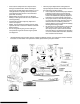
SECTION 3: UNPACKING & ASSEMBLING YOUR RIDER MOWER • • • • • Remove all screws and staples from crate. Holding the sides of the crate firmly, lift the top of the crate up and keep it aside. Avoid tire punctures. Remove and discard plastic bag covering the unit. Lift the rear of the mower and clear the bottom of the crate. Repeat for the front. Be sure parking brake is disengaged; roll unit out of the crate’s way. • • • • Loose Parts • 1. 2. 3. 4. 5.
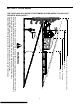
• • • • • Pivot the hood assembly up and lower the cutting height adjustment lever to the lowest position. Remove the two wing nuts (A and B in Figure 4 ) from two ends of the grasscatcher chute. Loosen the two wing nuts (C and D in Figure 4 ) in the middle of the chute. Do not remove. All four wing nuts hold the chute to the deck frame. Slide the grasscatcher chute to the right and out of the deck frame.
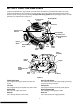
SECTION 4: KNOW YOUR RIDER MOWER Compare the illustrations in Figure 8 with your rider mower to familiarize yourself with the location of various controls and adjustments. The operation of any rider mower can result in foreign objects being thrown into the operator’s eyes, causing severe eye damage. Always wear safety glasses before operating the mower, or while performing any adjustments or repairs on it.
Cutting Height Adjustment Lever • Use to raise and lower the cutting deck which determines the cutting height. Before you move the shift lever to any of the positions, depress the brake pedal and stop the unit. Keep your foot on the brake pedal. Brake Pedal Use to stop the mower’s forward or reverse motion. Stopping Mower • • • • • Release blade engagement pedal all the way. Release the "Go" pedal and depress the brake pedal. When the mower comes to a complete stop, place the shift lever in neutral.
SECTION 5: OPERATING YOUR RIDER MOWER Using Throttle/Choke Control • The throttle/choke control is used to increase or decrease the speed of the engine.The FAST and the SLOW positions are marked with illustrations of a rabbit and a turtle respectively. See Figure 9. • • Starting Mower • • • For normal operation and when using a grass catcher, move the throttle/choke control to the FAST position.
• • • • Pivot the cover up. Pull up the grasscatcher bag by the handle and take it to the proper disposal site. See Figure 10 . Hold the bag away from your body. Push down on the bag lever and let the bottom section of the bag fall downwards. The grass clippings will be disposed of from the bottom. See Figure 10 . Tap the bag on the ground so that the three legs of the bag press against the ground. The bag lever should snap close while you push the bag downwards.
SECTION 6: MAKING ADJUSTMENTS “Go” Pedal WARNING: Do not at any time make any adjustment to riding mower without first stopping engine and disconnecting spark plug wire. Adjustment to the "Go" pedal is made at the cable end. See Figure 11 . • • • Brake Pedal During normal operation of the rider mower, the brake is subject to wear and tear. Check the brake periodically by carrying out the following test: • • • Release the parking brake and place the rider mower in neutral.
Seat Position • The seat position on the rider mower can be adjusted to maximize the operator’s convenience. • • • • • Stop the mower completely and engage the parking brake. Turn ignition off. Pivot the hood assembly up. Loosen the four self-tapping screws on the bottom of the seat. Slide the seat forward or backward in the slot, and position it as desired. Retighten the four screws.
• Completely loosen, but do not remove, the top hex nut out of the three hex nuts that hold the hex bolt and the ferrule on the deck hanger link assembly. Do not try to loosen or tighten the bottom nut. • • Thread the middle nut as far down as possible. When desired adjustment is reached, retighten the two nuts. Adjust both sides if necessary.
• • • • Using a 9/16” wrench, loosen the hex nut on the idler pulley. See Figure 15. Remove belt from around deck pulley, idler pulley, and the engine pulley. Place the new belt around the deck pulley and the engine pulley making sure that the belt is routed inside the belt keepers. There are two belt keepers under the grass catcher, one on the idler and the other under the deck belt cover. See Figure 15. Reinstall deck belt cover and secure with two selftapping screws, lock washer and hex nut.
SECTION 8: MAINTAINING YOUR RIDER MOWER General Recommendations • • • Always observe safety rules when performing any maintenance. The warranty on this rider mower does not cover items that have been subjected to operator abuse or negligence. To receive full value from the warranty, operator must maintain the rider mower as instructed in this manual. We do not recommend the use of pressure washers or garden hose to clean your unit.
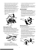
• Blade Assembly The spark plug should be cleaned and the gap reset once a season. Spark plug replacement is recommended at the start of each mowing season. Check engine manual for correct plug type and gap specifications. • Lubricate blade assembly and deck spindle only while reassembling the blade either after sharpening or replacement. Pivot Points NOTE: Your engine is equipped with a resistor spark plug, When replacing plug, make sure to use resistor type.
SECTION 9: OFF-SEASON STORAGE If the machine is to be inoperative for a period longer than 30 days, prepare for storage as follows. Rider Mower • Clean the engine and the entire unit thoroughly. • Lubricate all pivot points. Wipe the entire machine with an oiled rag to protect the surfaces. • Store unit in a clean, dry area. Do not store next to corrosive materials, such as fertilizer.
SECTION 10: TROUBLE-SHOOTING Trouble Excessive vibration Mower will not discharge grass or leaves uncut strips Broken Belt Belt comes off Belt shreds Engine will not crank Possible Cause Remedial Action 1. Bent or damaged blade 1. 2. Bent blade. 2. 1. 2. Engine speed low. Speed selection. 1. 2. 3. 4. Cutting height set too low. Blades short or dull. 3. 4. 1. Sudden stop or shock load to belt 1. 2. Incorrect belt used 2. 3. Belt engaged abruptly 3. 4.
Trouble Engine cranks but will not start Engine smokes Possible Cause Remedial Action 1. Throttle/choke not in starting position. 1. 2. 3. No fuel to the carburetor Fuel line or in-line fuel filter plugged 2. 3. 4. No spark to spark plug 4. 5. Faulty spark plug 5. 6. Dirty air cleaner 6. 1. 2. 3. Engine oil has been overfilled Dipstick not seated or broken Engine loses crankcase vacuum 1. 2. 3. Check owner's guide for correct position for throttle control/choke for starting.
SECTION 11: PARTS LIST FOR MODEL 1027 2 1 Ref. No. Part No. Description 1 731-2295 Steering Wheel 2 731-2296 Steering Wheel Insert 1 2 Ref. No. 4 3 7 5 7 5 8 6 22 Part No. Description 1. 731-1919 Steering Column: Black 2. 731-1857 Control Knob 3. 712-0142 Hex Nut 8-32 4. 710-3217 Pan Head Machine Screw #8-32 5. 710-0599 Hex Screw TT 1/4-20 x .50” 6. 710-0514 Hex Screw 3/8-16 x 1.0” 7. 712-0431 Lock Nut 8.
Model 1027 24 26 48 25 27 12 8 34 25 2 12 10 42 1 6 47 13 19 11 18 29 1 6 40 7 33 28 16 45 35 3 32 41 44 14 22 37 20 39 30 41 9 17 17 32 37 31 31 36 21 4 43 7 15 23 23 5
Model 1027 Ref. No. Part No. Description Ref. No. Part No. Description 1. 17962 Switch Plate 25. 731-0511 2. 650-0007 Steering Tube Assembly 26. 735-0265A Floor Pad: LH 3. 683-0033A Steering Support Bracket 27. 735-0266A Floor Pad: RH 4. 683-0178A Front Axle Assembly: RH 28. 736-0105 Bell Washer 5. 683-0179A Front Axle Assembly: LH 29. 736-0119 Lock Washer 6. 710-0224 30. 736-0160 Flat Washer 7. 710-0459A Hex Screw 3/8-24 x 1.5” Gr.5 Sp. 31. 736-0169 Lock Washer 8.
Model 1027 55 25
Model 1027 Ref. No. Part No. Description Ref. No. Part No. Description 1. 683-0155 Brake Pedal Assembly 30. 736-0329 Lock Washer 2. 683-0156 Variable Pedal Assembly 31. 736-0608 Spring Washer 3. 683-0275 Deck Pedal Assembly 32. 736-3000 Flat Washer 4. 683-0161 Shift Cam Assembly 33. 736-3019 Flat Washer .531 X 1.062 X .134 6. 710-1017 Ab Screw 1/4-14 X .625 34. 736-3020 Flat Washer .271 X .630 X .065 7. 711-0701 Clevis Pin 35. 738-0255 Shoulder Screw .375 Dia X .
Model 1027 27 8 25 27 5 22 14 3 19 16 26 28 12 13 23 19 29 1 6 18 21 10 21 7 17 24 11 Ref. No. Part No. 13 Description 20 1. 683-0152 Pivot Link Assembly 2. 683-0194 Lift Arm Assembly 3. 710-0376 Hex Screw 5/16-18 X 1.00 Gr.5 4. 710-3230 Hex Bolt 1/2-13 X 2.75 Gr.5 Special 2 4 9 5. 711-0332 Lift Bracket Pin Ref. No. 6. 711-1120 Lift Rod 18. 736-0119 Lock Washer 5/16 7. 711-3319 Ferrule 19. 736-0140 Flat Washer .385 I.D. x .620 O.D. 8.
Model 1027 4 9 12 8 14 3 6 7 10 11 5 13 1 2 Ref. No. 2 28 Part No. Description 1. 629-0865 Harness Assembly Adapter 2. 710-1208 Hex TT Screw 5/16-18 x 3.50 3. 710-0227 Hex Washer Head Self-Tap.Scew 4. 710-0805 Hex Screw 5/16-18 x 1.5 Gr. 5 5. 710-0642 Thd. Forming Scr. 1/4-20x .75 6. 712-3010 Hex Nut 5/16-18 7. 714-0115 Cotter Pin 8. 726-0320 Insulator Nut Plate 9. 736-0289 Shoulder Bushing 10. 736-0119 Lock Washer 5/16 11. 736-0173 Flat Washer .28 I.D. x .74 O.D.
Model 1027 2 8 30 15 32 20 15 6 22 7 13 9 10 19 17 23 27 5 12 2 14 31 25 1 25 22 24 18 29 26 23 7 15 9 4 Ref. No. 28 Part No. Description 11 1 683-0147 Idler Bracket Assembly 2 710-0191 Hex Screw 3/8-24 x 1.25 3 710-0314 Hex Screw 7/16-20 x 1.0” 4 710-0902 Cap Screw 3/8-24 x 3.75 16 5 710-1611 Pan Head TL Screw 5/16-18 x .75 3 6 710-3096 Hex Screw 3/8-16 x 2.0 Special 7 712-0116 Jam Lock Nut 3/8-24 8 712-0241 Hex Nut 3/8-24 Ref. No.
Model 1027 30 8 18 17 17 30 17 21 30 17 9 30 18 31 5 15 10 25 31 34 22 16 31 29 6 30 12 23 22 15 33 31 11 19 30 20 14 25 1 35 Ref. No. 1. 3. 4. 5. 6. 8. 9. 10. 11. 12. 14. 15. 16. 17. 18. 19. Part No. Description 783-0605 Deck Stabilizing Bracket 3 28 4 32 783-0564A Front Frame: Upper 783-08110716 683-0264 Steering Gear Cover Ref. No. Front Channel Assembly 783-0554 Cam Bracket 20. 21. 22. 23. 25. 28. 29. 30. 31. 32. 33. 34. 35.
Model 1027 45 46 A 46 B 28 47 25 10 33 33 14 17 36 12 11 4 3 7 38 22 39 16 27 32 5 42 26 A 43 41 B 31 18 19 28 30 9 35 20 8 21 15 1 44 34 15 29 12 24 40 2 28 6 20 29 37 31 11
Model 1027 Ref. No. Part No. 1. 2. 3. 4. 5. 6. 7. 8. 9. 10. 11. 12. 13. 14. 15. 16. 17. 18. 19. 20. 21. 22. 23. 24. Ref. No. Description 683-0149B Frame Assembly 683-0190A Frame Rail Support: RH 683-0191A Frame Rail Support: LH 683-0192 Muffler Pipe Extension 710-0148 Hex Fl. Screw #8-32 x 0.375 710-0157 Hex Screw 5/16-24 x .75” Gr.5 710-0599 Self-Tapping Screw 710-0624 Hex Screw 5/16-24 x 1.5” Gr.5 710-0654A TT Screw 3/8-16 x 1.0” 710-0871 Hex Slot Sems Screw #10-32 x 0.
Model 1027 17 11 15 6 3 7 1 9 1 11 10 8 4 2 1 1 1 3 3 12 13 Ref. No. Part No. Description 1. 710-0599 TT Screw 1/4-20 x 0.5 2. 710-0870 3. 16 Ref. No. Part No. Description 10. 783-0446 Plate: Hood TT Screw 3/8-16 x 0.62 11. 783-0447 Hood Bracket 710-1017 Torx AB Screw 1/4-14 x 0.625 12. 783-0448 Hood Bracket: Reinforcement 4. 720-0238 Rod End Grip 13. 783-0449 Hinge Bracket: Rear 6. 731-0511 Trim Strip 14. 783-0451A Pivot Plate: Rear Hood 7.
Model 1027 13 6 MTD 7 12 10 7 9 7 14 4 3 5 8 2 11 1 Ref. No. Part No. Description 1. 618-0232 Differential Assembly: Single Speed 2. 618-0248 Drive Shaft assembly: LH Brake 3. 618-0072B Upper Housing Assembly 4. 611-0114 Detent Shaft Assembly 5. 661-0006 Brake Yoke Assembly: LH 6. 710-1206 Hex Washer Hd. TT Screw 1/4-20 x 2.37 Gr.5 7. 710-1325 Hex Washer Hd. TT Screw 1/4-20 x 1.65 8. 717-0678 Brake Puck 9. 719-0313B Lower Housing 10. 732-0863 Spring Detent 11.
Model 1027 17 23 4 34 26 16 9 24 35 21 Ref. No. 19 27 8 36 6 8 33 31 25 29 3 37 26 32 22 7 18 39 9 20 38 14 5 2 14 11 20 20 28 14 5 9 22 24 13 12 10 1 30 15 Ref. No. Part No. Description Part No. Description 9. 710-0650 Self-Tapp. Screw 5/16-18 x .75 10. 710-0672 Hex Cap Scr. 5/16-24 x 1.25 11. 710-0932 Carriage Screw 12. 710-1611 Torx Screw 5/16-18 x .75 13. 712-0241 Hex Nut 3/8-24 14. 712-0397 Wing Nut With Bell Washer 15.
Model 1027 9 Ref. No. 16 9 3 23 3 9 9 22 23 25 1 2 23 23 23 23 11 14 5 11 11 26 20 11 7 21 4 10 27 24 23 13 12 17 23 24 15 18 6 19 8 36 Part No. Description 1 631-0060 Flow Indicator Assembly 2 631-0080 Grass Bag Assembly 3 710-0166 Machine Screw 1/4-20 x 1.0 4 710-0286 Machine Screw 1/4-20 x 0.5” 5 710-0456 Hex Screw #10-16 x 0.5” 6 710-0564 Hex Screw 1/4-20 x 2.75” 7 710-0642 Self-Tapping Screw 1/4-20 x 0.75” 8 710-0825 Hex Screw 1/4-20 x 3.
Model 1027 6 A B C D E 5 6 A B C DE 6 10 10 9 13 7 11 A B C D E 9 1 8 2 3 4 12 9 15 14 11 Ref. No. Part No. Description 1. 629-0945 Harness Assembly w/o relays 2. 725-0267 Ignition Switch: 5 Pin 725-1345 Ignition Key (not shown) 3. 725-1426 Solenoid: 12 V. 100 amp. 4. 725-1462 Seat Switch 5. 725-1643 Spring Switch 6. 725-1657A Interlock Switch 7. 725-1381 Fuse: 20 amp. 8. 725-1726 Battery Cover 9. 725-3237 Battery Cover: Red 10. 729-0125 Connecter 11.
Your Notes Date Comments 38
Your Notes Date Comments 39
MANUFACTURER’S LIMITED WARRANTY FOR: TWO-YEAR RESIDENTIAL ONE-YEAR COMMERCIAL Proper maintenance of your Cadet equipment is the owner’s responsibility. Follow the instructions in your operator’s manual for correct lubricants and maintenance schedule. Your Cub Cadet dealer carries a complete line of quality lubricants and filters for your equipment’s engine, transmission, chassis and attachments.