www.mymowerparts.com Service Manual Cub Cadet M48 Tank IMPORTANT: READ SAFETY RULES AND INSTRUCTIONS CAREFULLY This Service Manual is not a substitute for the Operator’s Manual. You must read, understand and follow all of the directions in this manual as well as the Operator’s Manual before working on this power equipment. CUB CADET LLC, P.O. BOX 361131, CLEVELAND, OH 44136-0019 PRINTED IN USA FORM NO.
www.mymowerparts.
www.mymowerparts.com TABLE OF CONTENTS M48 Tank .......................................................................................................... 1 About this Section ............................................................................................. 1 Changes for ‘03 and ‘04 .................................................................................... 1 Drive System Adjustment ..................................................................................
www.mymowerparts.
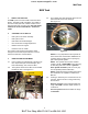
www.mymowerparts.com M48 Tank M48 Tank 1. 3.3. ABOUT THIS SECTION: The M48 is part of the Cub Cadet Commercial Tank Series. The 2004 model year M48 is very similar to The 2001 model year Tank. Earlier versions of this machine have been covered in the “2001 Cub Cadet Commercial Technical Handbook”: Form #77010528. 2.
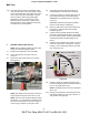
www.mymowerparts.com M48 Tank 3.5. 3.7. For complete brake adjustment procedures, refer to the “Brake Adjustment” section of this manual. For the purpose of tracking, insure that the brake linkage bellcranks and rods are well lubricated, not damaged, and work as intended. See Figure 3.5. If in doubt about the source of brake drag, disconnect the brake link rod from the actuator arm on the brake assembly. The actuator arm should return to center, releasing the brakes. See Figure 3.7.
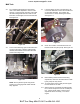
www.mymowerparts.com M48 Tank 3.12. If adjustment is necessary, remove the cutting deck. 3.14. Loosen the jam nuts at each end of the hydro control link rods, and rotate the rods to lengthen or shorten them. See Figure 3.14. 3.13. Inspect the return to neutral cylinders, rods, and bellcranks of the hydro control linkages. • The bellcranks should pivot easily without too much play. • The rods should not be bent, and the rod ends should not be loose.
www.mymowerparts.com M48 Tank 3.18. If one side does not drive as effectively as the other, test the output of the hydro pump to determine if the problem lies in the pump or the hydro motor. By the process of elimination, if performance is lacking, brake drag is eliminated, adjustment is correct, and the pump is O.K., then the problem is the motor. Pressure and flow tests will be used to determine if the pump is the the source of the problem. 4. 4.4.
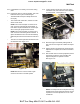
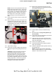
www.mymowerparts.com M48 Tank 4.15. Remove the stop bolt that sets the end of the travel of the lap bar that controls the hydro pump to be tested. See Figure 4.15. NOTE: The test can be performed at either line between the pump and the motor. The top line on the motor is the in line from the pump when driving forward. The linkage has more travel in forward than it does in reverse, so the test is most easily done on the top line of the pump, driving the pump in the forward direction forward. JAM NUT 4.11.
www.mymowerparts.com M48 Tank 4.27. Interpretation: flow droop greater than 1.5 GPM indicates a pump that is not performing as well as it should. 4.23. When the fluid is between 160-210 deg. f. (71-90 deg. c.) apply full forward drive pressure to the lap bar with the engine running at full speed (3600 RPM) while an assistant closes the valve to the point where pressure reaches 300 PSI (21 Bar.). See Figure 4.23. 10 GPM NOTE: A blocked filter may account for some loss of performance. 4.28.
www.mymowerparts.com M48 Tank 5.6. Remove the nut, washer, and cooling fan from the hydro pump to be replaced, using a 9/16” wrench. See Figure 5.6. FAN 5.10. Use a small two-jaw puller to remove the pulley from the tapered and keyed input shaft of the hydro pump. See Figure 5.10. NUT PULLER WASHER PULLEY Figure 5.10 Figure 5.6 5.7. Use a 3/8” breaker bar to move the belt tensioner pulley arm, slipping the belt off of the pulley. See Figure 5.7. 5.11.
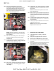
www.mymowerparts.com M48 Tank 5.20. Disconnect the two lines that connect the hydro motor to the back of the hydro pump using a pair of 7/8” wrenches. Plug the lines. See Figure 5.20. 5.14. Open the relief valve on the hydro pump that is to be tested. This will relieve any residual hydraulic pressure. See Figure 5.14. RETURN LINE FEED LINE CLOSE OPEN HYDRO PUMP ELBOW PRESSURE LINES BETWEEN PUMP AND MOTOR HYDRO MOTOR RELIEF VALVE ADAPTORS Figure 5.14 Figure 5.20 5.15.
www.mymowerparts.com M48 Tank 5.24. Remove the handle from the relief valve using a 7/16” wrench and a 3/16” allen wrench. 5.29. Position the pulley over the opening in the hydro pump support plate that the pump input shaft will pass through. 5.25. Remove the nuts from the carriage bolts that hold the hydro pump to the hydro pump mounting plate. See Figure 5.25. MOUNTING NUT 5.30.
www.mymowerparts.com M48 Tank 5.39. Install the wheels, lower the TANK to the ground, and test run it in a safe area. Make any necessary adjustments before installing the cutting deck. 6. REPLACING THE HYDRO MOTOR 6.1. If the cutting deck is currently on the unit, remove it. 6.2. Safely lift and support the rear of the tank. 6.3. Remove the rear wheels using a 3/4” socket. 6.4. Tilt the seat up, and disconnect the negative battery cable. 6.5.
www.mymowerparts.com M48 Tank 6.9. If the brake assembly is to be transferred to the new hydro motor: remove the cotter pin from the castle nut that holds the hub to the axle. 6.13. Disconnect the high pressure lines from the the hydro motor one at a time using a 7/8” wrench. A 1” wrench may be required to hold the fittings on the hydro motor. Plug the lines. See Figure 6.13. 6.10. Loosen, but do not remove the castle nut from the axle using a 11/2” socket.
www.mymowerparts.com M48 Tank 6.19. Safely fixture the hydro motor and brake assembly in a minimum 20 Ton press so that the ram presses against the end of the axle, and the assembly is supported by the edge of the brake drum. Press the drum off of the tapered shaft. 6.16. Withdraw the hydro motor, along with the three motor spacers, and place them gently on a work bench. See Figure 6.16. 6.20. Remove the castle nut and brake drum from the axle. See Figure 6.20.
www.mymowerparts.com M48 Tank 6.28. Install the brake arm and clip on the new hydro motor. See Figure 6.28. 7. BRAKE LINKAGE ADJUSTMENT 7.1. With the TANK parked on firm level ground, lift and safely support the back of the unit. 7.2. Remove the hairpin clips that hold the floor panel in position. 7.3. Lift the floor panel up using the grip opening at the top rear edge, slide it to the left, and remove it. See Figure 7.3. Figure 6.28 6.29.
www.mymowerparts.com M48 Tank 7.7. 7.11. Remove the hairpin clip and clevis pin that secures the clevis on the end of the brake connector rod to the rear brake arm assembly on both sides. See Figure 7.11. Loosen the jam nut that locks the shoulder nut in position on the brake connector rod using a 9/16” wrench and a 3/4” wrench. See Figure 7.7. REAR BELLCRANK SHAFT BRAKE LINK ROD SHOULDER NUTS BUSHING JAM NUTS REAR BRAKE ARM ASSEMBLY BRAKE CONNECTOR RODS BRAKE CONNECTOR ROD Figure 7.7 Figure 7.11 7.
www.mymowerparts.com M48 Tank 7.13. Confirm that the brake bearing hub, brake handle, and the brake rod that connects them move freely on the front bellcrank shaft. 7.16. Check the brake arm on the brake assembly for freedom of movement. It should return to center. 7.17. Reconnect the brake link rods and brake connecting rods to the rear brake arm assemblies. 7.14.
www.mymowerparts.com M48 Tank 7.21. Release the parking brake. 8. 7.22. The brake bracket should draw up against the frame cross member. If this reaction is not consistent, tighten the shoulder nut slightly. There should be roughly 1 1/2” between the head of the shoulder nut and the brake bracket when the brakes are applied. The M72 is based on the same frame design as the smaller members of the TANK series. Some changes have been made to accommodate the larger deck. 8.1.
www.mymowerparts.com M48 Tank 8.3. 8.5. The deck lift goes has finer increments of adjustment. See Figure 8.3. Figure 8.3 8.4. Heavier hardware connects the deck to the hangers. See Figure 8.5. Figure 8.5 8.6. The larger, heavier decks have a foot assist pedal to help raise and lower the deck. See Figure 8.4. Heavier front pivot bar and wider front track. See Figure 8.6. Figure 8.6 Figure 8.
www.mymowerparts.com M48 Tank 8.7. 8.9. The track at the rear has also increased. Extra brackets have been added to the frame to step the hydro motors out. See Figure 8.7. The parking brake lever has been moved up to a more convenient location. Figure 8.9 Figure 8.7 8.8. 8.10. A larger engine is required to power the larger deck and heavier total weight of the mower. A 28 H.P. Generac Guardian engine is employed. See Figure 8.10.
www.mymowerparts.com M48 Tank 9. OTHER TANK FEATURES 9.1. Honda Power is offered on the M48-HN and M54-HN. The M48-HN has a 20 H.P. Honda Vtwin engine. The M54-HN has a 24 H.P. Honda V-twin. See Figure 9.1. 9.3. The TANK exhaust systems all feature a new aluminized finish. This finish resists corrosion better than the heat paint that is more commonly used. It also dissipates heat more effectively, producing noticeable improvements on chassis dynamometers. See Figure 9.3. Figure 9.1 Figure 9.3 9.2.
www.mymowerparts.com M48 Tank 9.6. 1/4” increments on the height adjuster, with foot assist deck lift. See Figure 9.6. 9.8. Figure 9.8 Figure 9.6 9.7. Heavy duty spherical rod ends on the arms at the front of the deck. See Figure 9.8. The deck belt release operates in a vertical plane. It can be tensioned with foot pressure, and the rear wheel does not interfere with its travel. See Figure 9.7. 9.9. The arms themselves are cast iron, and the liftshaft is heavier. See Figure 9.9. Figure 9.
www.mymowerparts.com M48 Tank 9.10. The deck itself features reversible caster wheel brackets. The same part number applies to both the left and the right brackets. See Figure 9.10. 9.12. The deck support plates are larger this year, to prevent plate bending and separation. See Figure 9.12. Figure 9.10 Figure 9.12 9.13. The baffling, airflow, and strength of the deck have all received some improvements this year. 9.11. Improved self-aligning pillow blocks now suspend the deck. See Figure 9.11. 9.14.
www.mymowerparts.com M48 Tank 9.17. The under-deck baffling has been reinforced, and a “stealth baffle” has been added between the second and third blades. See Figure 9.17. 9.15. A guiding baffle near the rear of the opening helps direct the clippings out from under the deck. See Figure 9.15. Figure 9.17 Figure 9.15 9.16.
www.mymowerparts.com M48 Tank 10. 10.1. For 2004, one model of TANK will be offered with a Kohler 28 H.P. EFI engine. That unit is a 60” Wide-Track model. That model is built on the widened M72 frame, but features a 60” deck. KOHLER EFI Fuel injection is nothing new. The Wright flyer that made history above the dunes at Kitty hawk, North Carolina was fuel injected. That was a hundred years ago this past summer. That system was only slightly more complex than a cam-driven Windex bottle.
www.mymowerparts.com M48 Tank 10.5. The return lines each lead back to the tank from a tee fitting just beneath the tee fitting for the fuel feed lines. The return fuel comes from the fuel pressure regulator. NOTE: The fuel pump is protected by an internal 60µ filter. 10.7. The pump sends pressurized fuel to the fuel pressure regulator. The regulator maintains a constant down-stream pressure of between 36 and 42 PSI. See Figure 10.7.
www.mymowerparts.com M48 Tank 10.8. There are two lines exiting the pressure regulator. One is a regulated pressure line that feeds the fuel rail via the fuel filter. The second line is a return line. The third line is a high pressure feed from the fuel pump. See Figure 10.8. 10.9. The fuel filter is easily accessible. See Figure 10.9. Regulated pressure to rail, via filter Vacuum barb (not used for this application) From pump To fuel rail Fuel filter Return to tanks Figure 10.
www.mymowerparts.com M48 Tank 11. Cap for shrader valve Fuel rail EFI CONTROLS The Fuel injection system used by Kohler is an adapted version of the Bosch Motronic automotive system. NOTE: Do not connect or disconnect any electrical components with the key switch in the “on” position. The resulting arc could cause immediate and sever damage to the ECU. electrical connection for injector NOTE: If using a circuit tester, use only a high impedance tester (eg. Thexton model 125).
www.mymowerparts.com M48 Tank 11.4. The fuel pressure at the injectors is held constant by the fuel pressure regulator. The amount of fuel delivered to the cylinders is controlled by the length of time that the individual fuel injectors are triggered. The length of time the injectors are triggered varies from 1.5 to 8.0 milliseconds. 11.9. The ignition coils are also controlled by the ECU. Each cylinder has its own coil. See Figure 11.9. 11.5. Both injectors are triggered simultaneously.
www.mymowerparts.com M48 Tank • Do not connect a battery charger to the TANK with the key switch turned on. • The ECU requires at least 7.0 volts to function. • If the battery goes dead, or is disconnected, the adaptive memory in the ECU will be cleared. It will take 10-15 minutes of running, at normal operating temperatures, under a variety of loads and throttle settings to re-learn the full envelope of performance. Clearing the memory will also clear diagnostic trouble codes.
www.mymowerparts.com M48 Tank • Crank triggers are generally an all-or-nothing proposition: they work perfectly or not at all. In extremely rare instances, a failed crankshaft trigger will not keep-up with the speed of the engine. It will work at low speed, but cause intermittent ignition and injector action at higher speeds. This will result in staccato misses and backfires. 11.15. The exhaust gas oxygen (O2) sensor contains a palladium insert.