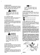
Cub Cavalcade Owner’s | electrostatic HOME Manual | crosiers and Model Numbers ead Sa Instructions Carefully };18 ggg; an American-built product. CUB CADET CORPORATION « P.O. BOX 36930 » CLEVELAND, OHIO 44136 PRINTED IN U.S.A. FORM NO.
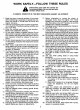
Serial No. Location . . L2 Safe Operations . Controls Operation . . Adjustments Maintenance . . Oft-Season Storage. . Serial number plate is located on left hand side frame. NOTE: LEFT and RIGHT indicate the left and right sides of the tractor when facing forward in the driver’s seat. Reference to FRONT indicates the grille end of the tractor; to REAR the draw bar end. CHASSIS S/N ENGINE S/N MODEL NETS Mowing Deck—Adjustment and Operation . . .
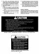
WORK SAFELY—FOLLOW THESE RULES A Instructions given with this symbol are tor personal safety. Be sure you and your workers follow them. A CAREFUL OPERATOR 1S THE BEST INSURANCE AGAINST AN ACCIDENT . Read this owner's manual carefully in its entirety before attempting to assemble or operate this unit. Keep this manual in a sale place for future and regular reference. . This unit is a precision piece of power equipment, not a plaything. Therefore exercise extreme caution at all times. .
31, 32. 33 The vehicle and attachments should be stopped and inspected for damage after striking a foreign object. The damage should be repaired before restarting and operating the equipment. Do not change the engine governor settings or overspend the engine. When using the vehicle with mower, proceed as follows: 34, 35. Look behind to make sure the area is clear before placing the transmission in reverse and continue looking behind while backing up.
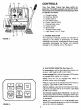
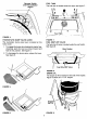
FIGURE 1. FIGURE 2. CONTROLS Your Cub Cadet Tractor has been safety engineered. Thoroughly acquaint yourself with all the instruments and controls before attempting to start or operate the tractor. . Charge Indicator . Electronic Monitor . ignition Switch . Lift Contort Lever . Power Take-Off (PTO) Parking Brake Lever . Choke Contort . Brake Pedal Throttle Control Lever Light Switch {16 H.P. Only) Coimbatore A.
C. IGNITION SWITCH The ignition switch is a three position switch. Turn key to “START" position when engine starts, then release key. Key will retract to “ON" position. Turn key to “OFF” position to stop engine. See figure 1. A T Remove the key from the tractor when the tractor is not in use to prevent accidental starting and battery discharge. D. LIFT CONTROL LEVER This control lever is used to raise and lower the cutting deck and other attachments, See figure 1. E.
Reverse Switch FUEL TANK and PTO Indicator Switch The fuel tank is located under the seat. See figure 7. FIGURE 4. HYDRO STATIC DUMP VALVE LEVER FIGURE 7. The hydro static dump naive lever is located on the FUEL SHUT-OFF VALVE frame cover. The fuel shut-off valve is located under the rear fender. 1. To engage the dump valve (making the tractor free See figure 8. wheeling), push the lever as shown forward and Rear Fender hold in this position. See figure 5. 2.
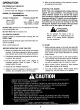
OPERATION PER-OPERATION CHECKLIST 1. Check Oil Level 2. Fill Fue! Tank with Regular or Unleaded Gasoline ENGINE OIL REQUIREMENTS RECOMMENDED OIL Ambient Temperature Viscosity (Grade 5F) Above 40°F SAE 30 0°F to 100°F SAE 10W30 or 10W40 Below 20°F SAE 5W20 or 5W30 DO NOT USE: Synthetic oil, non-detergent oit or other non-recommended oils. DO NOT MIX different brands of oil. OIL DIPSTICK CHECKS Dipstick should be checked before starting the unit EVERY TIME.
TO SHUT OFF 1. Return speed control lever to neutral, depress brake, engage parking brake and return PTO to off position. 2. Move throttle to slow position. 3. Turn key to off position and remove. CAUTION During operation do not run the engine in confined area such as storage building. Immediately move the tractor outside of the building. Exhaust fumes can kil Never run engines inside buildings. DRIVING THE TRACTOR 1.
Avoid turns when driving on a slope. If a turn must be made, turn down the slope. Turning up a slope greatly increases the chance of a roll over. Avoid stopping when driving up a slope. If it is necessary to stop while driving up a slope, start up smoothly and carefully to reduce the possibility of flipping the tractor over backward, STOPPING THE TRACTOR Move the speed control lever to the “N” position or depress the brake pedal.
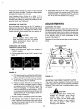
Using a feeler gauge, check the air gap. See figure 15. Insert feeler gauge into one of three access slots located around the outside of the brake plate. The air gap should be Adjust the self-locking nuts to obtain the proper clearance. Repeat the operation in all three access slots. NOTE: If brake plate drags on clutch at inches air gap, increase air gap to .020-inches. After two hours of use, recheck and set back 10 .010-015 inches. If the above procedure does not work, see your authorized dealer.
Actuating Strap FIGURE 16, HYDRO STATIC TRANSMISSION CONTROL ADJUSTMENT 1. Block the rear of the tractor up so both rear wheels are off the ground. 2. Remove the cotter pin and clevis pin from turnbuckle (B) at actuating arm assembly. See figure 16. 3. Thread the turnbuckle inward or outward one or WO turns. 4. Replace the turnbuckle and clevis pin. 5. Start the engine and run at idle speed. 6. if rear wheels do not turn, turnbuckle (B) is adjusted properly. 7. Shut off the engine. 8.
LIFT CONTROL LEVER The lift control lever is used to lift or lower equipment used with the tractor. The equipment can be set in five positions by depressing the bunion on the lever and releasing it when the desired position is reached. See figure 19. FIGURE 19. BELT ADJUSTMENT For belt adjustment information, refer to page 17. MAINTENANCE ENGINE OIL The engine crankcase is filled with ship-away ail. This oil may be used for the first § hours of engine operation at temperatures between + 90 degrees F.
AIR CLEANER (16 H.P. Units) Servicing Foam Pr-Cleaner Element Clean and re-oil foam per-cleaner element at 3 month intervals or every 25 hours, whichever occurs first. NOTE: Service more often under dusty conditions. 1, Remove knob and cover. See figure 21. 2. Remove foam per-cleaner element by sliding it up off the paper cartridges. 3. a. Wash per-cleaner element in liquid detergent and water. b. Squeeze dry in cloth. c. Saturate in engine oil. Squeeze 1o distribute oil evenly. d.
If frequent additions are required, locate the leak and correct, Inadequate supply of fluid may result in permanent internal damage. If contaminant is observed on the reservoir/expansion tank screen, poor maintenance is indicated. Remove the reservoir/expansion tank, wash clean, dry and reinstall. If the screen is pierced, the reservoir/expansion tank should be replaced. NOTE The threads on the reservoir/expansion tank are left hand thread.
NOTE When reassembling torque bracket, be certain center of torque bracket is lined up with center of engine shaft. 3. Unhook the spring on the idler pulley from the spring bracket, located near the engine pulley. See figure 26. Spring Bracket FIGURE 28. 6. Lift belt over pulley on hydro static pump. Turn fan at pump by hand to remove belt. See figure 29. FIGURE 26. 4. Remove the idler pulley at hydro static pump by removing 3/8” hex bolt, hex nut, vaudeville washer and flat washer. See figure 27.
Stationary idler Bracket FIGURE 30. BATTERY INFORMATION A GEE . Battery acid must be handled with great care as contact with it can burn and blister the skin. Iris also advisable to wear protective clothing (goggles, rubber gloves and apron) when working with it.* . Should battery acid accidentally splatter into the eyes or onto the face, rinse the affected area immediately with clean cold water and seek prompt medical attention. .
BATTERY REMOVAL OR INSTALLATION A oy When removing the battery, follow this order of disassembly 1o prevent your wrench from shorting against the frame, 1. Remove the Negative cable. 2. Remove the Positive cable. To install a battery: 1. Attach the Positive cable. 2. Almach the Negative cable. BOOSTER BATTERIES AND CHARGING THE BATTERY CAUTION Batteries can explode during boosting or charging. Always wear proper eye protection, such as safety goggles.
OFF-SEASON STORAGE + If the machine is to be inoperative for a period longer than 30 days, the following procedures are recommended: 5 1. Remove dirty engine oil, fill with new oil and run the engine for about 5§ minutes to let the oil circulate to all the parts. 2. Always set the throttle lever on “OFF™ position. 3. Check all the bolts and nuts, and tighten if necessary. Remove the battery from the tractor recharge it, and adjust the electrolyte level. Store the battery in a dry and dark place.
Side to Side Leveling The 36 and 44 inch mowers are equipped with two adjustable lift links. This feature allows the mower o be leveled. See figure 32, Lift Link (Right Hand Sade Shown) FIGURE 32. To check the side to side leveling of the deck, place the unit on a hard, level surface. Disconnect the spark plug wire(s). Place the two outer blades parallel to the unit. Measure the distance from the front tip of blade 1o the surface on each side.
NOTE When installing a new belt always check the condition of the pulleys and if they are not in satisfactory condition, replace them with new pulleys available at your authorized dealer. NOTE Be sure narrow dimension of belt is in bottom of all pulley grooves. Stop the tractor, disengage the power take-off, place all controls in neutral, engage the brake lock and stop the engine before performing any maintenance.
the India pulley uts arg yo. moved for any season, that Should tightener Jof g {122 1o 149 Nerdy torque when re. Placed. coat of jf Prevent try.
Spindle Mower (See figures 40, 41 and 42.} To replace spindle drive belt, remove belt covers, Release spring tension. Remove the old belt. Install the new belt around pulleys as shown. Be certain belt is in the lower groove of the center pulley. Reinstall bat covers. Belt FIGURE 42. FIGURE 44, 23 MOWING A To avoid possible injury, do not allow anyone in the area opposite the discharge chute while mowing.
Never direct discharge of material toward by-standers nor allow anyone near the machine while in operation. ATTACHING MOWER TO TRACTOR 36-inch deck-assemble the front hanger assembly to the tractor as shown in figure 46. Hairpin Cotters and Flat Washers Front Hanger Assembly Hairpin Cotter and Flat Washer FIGURE 46. 44-inch deck—assemble the front hanger assembly to the tractor as shown in figure 47, 24 Hairpin Cotter and Flat Washer Hairpin Cotter and Flat Washer FIGURE 47.
Hairpin Cotter Pull tidier pulley on tractor toward the outside of the unit and Flat Washer and place belt behind tidier pulley. See figure 52. e Idler Pulley p Hairpin Cotter \ and Flat Washer — FIGURE Side of 44-inch Deck Install spindle belt by slipping belt over electric PTO pulley. See figure 51. FIGURE 52. Electric PTO Pulley FIGURE 51.
TROUBLE SHOOTING Possible Cause Possible Remedy LACK OF POWER Choke partially closed . .. Open choke. Restricted air filter element . Clean or replace element. Carburetor improperly adjusted Adjust carburetor. Faulty ignition . Check spark plug.” HARD TO START OR WILL NOT START No gasoline in fuel tank or Fill the fuel tank with non-leaded or regular gasoline and check the carburetor, and fuel shut-off valve. Engine will not crank The Lawn Tractor has an interlock safety starting system.
SPECIFICATIONS 1110 (293) 1610 (393) CAPACITIES (Approximate} Cadet Cadet Fuel Tank 3 Gallon Crankcase . L 3 Pints Transmission Hydro static 1% Pints Trans axle 23 Pints ENGINE Briggs and Castration Preregistration Make and Model . 253707 402707 Number of Cylinders One Two . . .. Stroke e .. Displacement. 24.36 cu. in. 40.0 cu. in. Engine speed (Governed) Minimized. . 1800 RPM Maximum no load speed (Highlander) .. 3500 3400 Valve clearance (Engine Cold) Intake . .. ELECTRICAL SYSTEM Ignition . . .
LUBRICATION TABLE Check | Change Anticipated Air Temperature Point of Lubrication at at Hours Hours | Capacity, Above 40°F. +0°F. to 100°F. Below 20°F. Engine crankcase Check Every 3 pints Engine Ol Engine Qi Engine Qil before 30 SADES SAE10W30 or SALESWOMAN each SAE10W40 SALESWOMAN Cub Cadet Hydraulic Transmission Fluid Note: Cub Cadet Hydraulic Transmission Fluid meets Hydro-drive unit 30 Add as 14 pt. jiH B-6 Specifications. !f fluid is used that does not mounted on needed. | Approx.
STANDARD TORQUE DATA FOR INCH NUTS AND BOLTS— FOOT POUNDS Recommended torque for all Standard Unplaced Noels and Bolts, provided: A. Surface finish is oxide coated, oil quenched or bright. B. Al thread surfaces are clean and lubricated with SEA-30 engine oil or equivalent (See NOTE). €. Saints are rigid, that Is, no gaskets or compressible materials are used. D. When reusing nuts ot bolts use minimum tongue values. NOTE: Multiply the standard torque by: -85 when finished jam nuts are used.