Safe Operation Practices • Set-Up • Operation • Maintenance • Service • Troubleshooting • Warranty Operator’s Manual CC 30 WARNING READ AND FOLLOW ALL SAFETY RULES AND INSTRUCTIONS IN THIS MANUAL BEFORE ATTEMPTING TO OPERATE THIS MACHINE. FAILURE TO COMPLY WITH THESE INSTRUCTIONS MAY RESULT IN PERSONAL INJURY. CUB CADET LLC, P.O. BOX 361131 CLEVELAND, OHIO 44136-0019 Printed In USA Form No.
1 To The Owner Thank You Thank you for purchasing a lawn tractor manufactured by Cab Cadet. It was carefully engineered to provide excellent performance when properly operated and maintained. If applicable, the power testing information used to establish the power rating of the engine equipped on this machine can be found at www.opei.org or the engine manufacturer’s web site. Please read this entire manual prior to operating the equipment.
Important Safe Operation Practices 2 WARNING! This symbol points out important safety instructions which, if not followed, could endanger the personal safety and/or property of yourself and others. Read and follow all instructions in this manual before attempting to operate this machine. Failure to comply with these instructions may result in personal injury. When you see this symbol.
12. A missing or damaged discharge cover can cause blade contact or thrown object injuries. 13. Stop the blade(s) when crossing gravel drives, walks, or roads and while not cutting grass. 14. Watch for traffic when operating near or crossing roadways. This machine is not intended for use on any public roadway. 15. Do not operate the machine while under the influence of alcohol or drugs. 16. Mow only in daylight or good artificial light. 17. Never carry passengers. 18.
Children Service 1. Safe Handling of Gasoline: Tragic accidents can occur if the operator is not alert to the presence of children. Children are often attracted to the machine and the mowing activity. They do not understand the dangers. Never assume that children will remain where you last saw them. a. Keep children out of the mowing area and in watchful care of a responsible adult other than the operator. b. Be alert and turn machine off if a child enters the area. c.
Periodically check to make sure the blades come to complete stop within approximately (5) five seconds after operating the blade disengagement control. If the blades do not stop within the this time frame, your machine should be serviced professionally by an authorized MTD Service Dealer. Do not modify engine 4. Check brake operation frequently as it is subjected to wear during normal operation. Adjust and service as required. Notice Regarding Emissions 5.
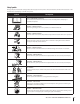
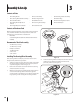
Safety Symbols This page depicts and describes safety symbols that may appear on this product. Read, understand, and follow all instructions on the machine before attempting to assemble and operate. Symbol Description READ THE OPERATOR’S MANUAL(S) Read, understand, and follow all instructions in the manual(s) before attempting to assemble and operate DANGER— ROTATING BLADES Never carry passengers. Never carry children, even with the blades off.
Symbol Description WARNING—GASOLINE IS FLAMMABLE Allow the engine to cool at least two minutes before refueling. WARNING— CARBON MONOXIDE Never run an engine indoors or in a poorly ventilated area. Engine exhaust contains carbon monoxide, an odorless and deadly gas. DANGER— ROTATING BLADES Do not step on the cutting deck.
(OK) Figure 1 Slope Gauge 12° Slope e °d a s h e d lin 12 USE THIS SLOPE GAUGE TO DETERMINE IF A SLOPE IS TOO STEEP FOR SAFE OPERATION! To check the slope, proceed as follows: 1. Remove this page and fold along the dashed line. 2. Locate a vertical object on or behind the slope (e.g. a pole, building, fence, tree, etc.) 3. Align either side of the slope gauge with the object (See Figure 1 and Figure 2 ). 4. Adjust gauge up or down until the left corner touches the slope (See Figure 1 and Figure 2). 5.
3 Assembly & Set-Up Contents of Crate • One Riding Mower • One Seat Assembly • One Discharge Chute Assembly • One Steering Wheel/Shaft Assembly • One Rear Engine Cover • One Mulch Plug • One Rear Hitch Plate • One Oil Drain Sleeve • One Product Registration Card • One Riding Mower Operator’s Manual • One Steering Pedestal Cap • One Front Bumper • One Engine Operator’s Manual • One Hardware Pack Contents of Hardware Pack Before beginning installation, remove all the contents from
5. Tighten the shoulder bolt and lock nut using a 9/16” wrench and 7/16”wrench or socket. 6. Remove the pedestal cap mount hex screw factory installed and located on the tractor’s steering console. Retain the screw for later instructions. 7. Slide the Pedestal cap down onto the tractor (1) and slighty rotate to the right to clip into place. Secure the pedestal with the hex screw (2) previously removed. See Figure 3-3. 2 1 Figure 3-5 3.
6. Install the two shoulder bolts and lock nuts removed from the seat mounting bracket in Step 1. See Figure 3-7. 1 2 Adjustment Knob Figure 3-8 Figure 3-7 Installing the Mulch Plug WARNING! NEVER operate this tractor without either the mulch plug or deck chute installed. Note: Make sure that the bolt’s shoulder is completely recessed into the seat bracket when securing the lock nut. 7. To adjust the position of the seat, remove the adjustment knob on the bottom of the seat.
Install The Rear Engine Cover Installing the Bumper 1. 1. Remove the two screws as shown in Figure 3-12. 2. Position the bumper over the mounting holes and secure using the hardware removed in Step 1, as shown in Figure 3-12. 2. Remove the two factory installed hex screws located on the rear engine cover. Retain the screws for later instructions. See Figure 3-10. Install the rear engine cover by positioning it in place as shown in Figure 3-10.
2. Remove the plastic cover, if present, from the positive battery terminal and attach the red cable to the positive battery terminal (+) with one of the bolts and hex nuts, previously removed, using a 7/16 inch wrench and socket. See Figure 3-13. Tire Pressure WARNING! Equal tire pressure should be maintained at all times. Never exceed the maximum inflation pressure shown on the sidewall of the tire.
4 Controls & Features Clutch/Brake Pedal Speed Control & Parking Brake Lever Fuel Level Indicator Ignition Switch Module Shift Lever Fuel Fill Cap Throttle/Choke Lever Deck Lift Lever Cup Holder Oil Fill Cap PTO (Blade Engage) Lever Figure 4-1 Lawn Tractor controls and features are illustrated in Figure 4-1 and described on the following pages.
Throttle / Choke Control Ignition Switch Module The throttle control lever is located on the left fender of the tractor seated in the operator’s position, see Figure 4-1. This lever controls the speed of the engine, as well as the choke when it is pushed all the way forward. When set in a given position, the throttle will maintain a uniform engine speed. The ignition switch module is located on the left fender of the tractor seated in the operator’s position, adjacent to the Throttle/ Choke Control.
Shift Lever Fuel Lever Indicator The shift lever is located on the control panel just below the seat, in the center of the tractor. It has three positions, FORWARD, NEUTRAL and REVERSE. The brake pedal must be completely depressed and the tractor must not be in motion when moving the shift lever. See Figure 4-4. The Fuel Lever Indicator is located below the seat on the left hand side from the operator’s position in the controls panel. Use this window to identify the tractor’s fuel needs. See Figure 4-5.
5 Operation WARNING • • • • • • • • • • • • Avoid Serious Injury or Death Know location and function of all controls. Remove objects which could be thrown by the blades. Go up and down slopes, not across. Use extra caution on slopes. Do not mow slopes greater than 12 degrees. Avoid sudden turns. Use low speed. Do not operate machine where it could tip or slip. If machine stops going uphill, stop blades and back down slowly.
Stopping the Engine WARNING! If you strike a foreign object, stop the engine, disconnect the spark plug wire and ground against the engine. Thoroughly inspect the machine for any damage. Repair the damage before restarting and operating. 1. If the blade is engaged, place the PTO (Blade Engage) lever in the disengaged (OFF) position. 2. Place the throttle/choke control near the SLOW position. 3. Turn the ignition key counterclockwise to the STOP position. 4.
4. Once activated (indicator light ON), the tractor can be driven in reverse with the cutting blade (PTO) engaged. 5. Always look down and behind before and while backing to make sure no children are around. After resuming forward motion, return the key to the NORMAL MOWING position. The REVERSE CAUTION MODE will remain activated until: a. The key is placed in either the NORMAL MOWING position or STOP position or b. The operator leaves the seat.
Mulching A mulch kit has been supplied with your unit. Mulching is a process of recirculating grass clippings repeatedly beneath the cutting deck. The ultra-fine clippings are then forced back into the lawn where they act as a natural fertilizer. Refer to the Assembly & Set-up section of this manual for instructions on how to install the mulch kit. Using the Deck Lift Lever To raise the cutting deck, move the deck lift lever to the left, then place it in the notch best suited for your application.
6 Maintenance & Adjustments Maintenance 6. WARNING: Before performing any maintenance or repairs, disengage PTO, move shift lever into neutral position, set parking brake, stop engine and remove key to prevent unintended starting. Tip the tractor slightly in the direction of the suitable container to aid in fully draining all of the oil from the engine. WARNING! Before tipping engine or equipment to drain oil, drain fuel from tank by running engine until fuel tank is empty.
Steering Rack & Pinion Battery Once per season, or every 25 hours of operation, it will be necessary to lubricate the steering rack and pinion gear located under the front of the unit. Using standard automotive grease, apply grease to the front side and rear side of the steering rack, as indicated in Figure 6-2. • The battery is sealed and is maintenance-free. Acid levels cannot be checked. • • Always keep the battery cables and terminals clean and free of corrosive build-up.
4. Attach the hose coupler to the water port on your decks surface. See Figure 6-3. Parking Brake Adjustment WARNING: Never attempt to adjust the brakes while the engine is running. Always disengage PTO, move shift lever into neutral position, stop engine and remove key to prevent unintended starting. If the tractor does not come to a complete stop when the brake pedal is completely depressed, or if the tractor’s rear wheels can roll with the parking brake applied, the brake is in need of adjustment.
Tires WARNING! Gasoline is a toxic substance. Dispose of gasoline properly. Contact your local authorities for approved disposal methods. WARNING! Never exceed the maximum inflation pressure shown on the sidewall of the tire. • The recommended operating tire pressure is: • Approximately 10 psi for the rear tires • Approximately 14 psi for the front tires IMPORTANT: Refer to the tire sidewall for exact tire manufacturer’s recommended or maximum psi. Do not overinflate.
Maintenance Schedule Check Engine Oil Level Check Air Filter for Dirty, Loose or Damaged Parts Before Each use Every 10 Hours P P P Clean and Re-oil Air Filter’s Foam Pre-cleaner Every 25 Hours Every 50 Hours P Replace Air Filter Element Change Engine Oil and Replace Oil Filter P (if Equipped) Lube Front Axles and Rims Clean Engine Cooling Fins Check Spark Plug Condition & Gap Replace Fuel Filter Prior to Storing P (if Equipped) Clean Battery Terminals Every 100 Hours P P P P P P P P P
7 Service Cutting Deck Removal 5. To remove the cutting deck, proceed as follows: 1. Place the PTO (Blade Engage) lever in the disengaged (OFF) position and engage the parking brake. 2. Lower the deck by moving the deck lift lever into the bottom notch on the right fender. 3. Remove the bow-tie cotter pin and flat washer from the deck lift assembly, and retain for reinstallation later. See Figure 7-1. Remove the remaining bow-tie cotter pins securing the deck to the unit, as shown in Figure 7-3.
Changing the Deck Belt 6. NOTE: It is possible to change the deck belt with the cutting deck still installed on the tractor, however it is much easier to remove the deck first, change the deck belt, then reinstall the cutting deck. Remove the belt keeper by removing the hex bolt that secures it. See Figure 7-6. To change the cutting deck belt, proceed as follows: 1. It is easiest to change the deck belt by first removing the cutting deck as instructed earlier in this section first.
Jump Starting Cutting Blade WARNING! Never jump start a damaged or frozen battery. Be certain the vehicles do not touch, and ignitions are off. Do not allow cable clamps to touch. 1. WARNING! Shut the engine off and remove ignition key before removing the cutting blade(s) for sharpening or replacement. Protect your hands by using heavy gloves when grasping the blade. Connect positive (+) cable to positive post (+) of your tractor’s discharged battery. 2.
4. To properly sharpen the cutting blades, remove equal amounts of metal from both ends of the blades along the cutting edges, parallel to the trailing edge, at a 25°- to 30° angle. Always grind each cutting blade edge equally to maintain proper blade balance. See Figure 7-8. Figure 7-8 WARNING! If the cutting edge of the blade has previously been sharpened, or if any metal separation is present, replace the blades with new ones.
8 Troubleshooting Problem Engine fails to start Cause Remedy 1. PTO/Blade engaged 1. Place blade engage lever in disengaged (OFF) position. 2. Spark plug wire disconnected 2. Connect wire to spark plug. 3. Fuel tank empty, or stale fuel 3. Fill tank with clean, fresh (less than 30 days old) gas. 4. Choke not activated 4. Place the throttle control in CHOKE position. 5. Faulty spark plug 5. Clean, adjust gap or replace plug. 6. Blown fuse 6. Replace fuse(s) 7. Engine flooded 7.
9 Replacement Parts Component Part Number and Description 954-05001 Drive Belt (Mowing Deck) 918-04822A Deck Spindle 942-04385 Cutting Blade (30”) 925-1707D Battery 951-12179B Fuel Tank Cap 625-05000 Key Asm-Key W/Keychain 734-0298 Tire (Front), 13.0 x 5.0-6.00 734-04641 Tire (Rear) 16 x 6.
10 Attachments & Accessories The following attachments and accessories are compatible for Cub Cadet CC-30 riding lawn mower. See your Cub Cadet dealer for information regarding price and availability of these attachments and accessories. Caution: Cub Cadet CC-30 riding lawn mowers are NOT designed for use with any type of ground-engaging attachments (e.g. tiller or moldboard plow). Use of this type of equipment WILL void the tractor’s warranty.
FEDERAL and/or CALIFORNIA EMISSION CONTROL WARRANTY STATEMENT YOUR WARRANTY RIGHTS AND OBLIGATIONS MTD Consumer Group Inc, the United States Environmental Protection Agency (EPA), and for those products certified for sale in the state of California, the California Air Resources Board (CARB) are pleased to explain the evaporative emission control system (ECS) warranty on your 2013-2014 small off-road equipment (outdoor equipment).
WARRANTED PARTS: The repair or replacement of any warranted part otherwise eligible for warranty coverage may be excluded from such warranty coverage if MTD Consumer Group Inc demonstrates that the outdoor equipment has been abused, neglected, or improperly maintained, and that such abuse, neglect, or improper maintenance was the direct cause of the need for repair or replacement of the part.
CUB CADET LLC MANUFACTURER’S LIMITED WARRANTY FOR CC-30 RIDER IMPORTANT: To obtain warranty coverage owner must present an original proof of purchase and applicable maintenance records to the servicing dealer. Please see the operator’s manual for information on required maintenance and service intervals.