
Product Manual


Assembly & Set-Up
3
10
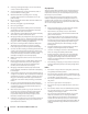
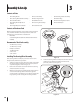
Figure 3-1
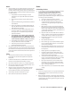
4. Lower the steering wheel assembly onto the lower steering
shaft and secure with the shoulder bolt and lock nut
previously removed. See Figure 3-2.
1
2
2
Figure 3-2
Contents of Hardware Pack
Before beginning installation, remove all the contents from the
crate and all the hardware from the pack from to make sure
everything is present. Hardware is listed below.
• Hitch Plate
• Seat Mounting Bracket (with two shoulder bolts & lock nuts
installed)
Recommended Tools for Assembly
• 3/8” Wrench (or socket)
• 1/2” Wrench (or socket)
• Phillips Screw Driver
• 1/4” Drive Ratchet
• 9/16” Socket
• 7/16” wrench
Installing The Steering Wheel Assembly
If the steering wheel assembly for your tractor did not come
alredy installed, follow the steps below:
1. Slide the pedestal cap onto the steering shaft so that when
the steering shaft is installed on the tractor, the pedestal
cap will be upright as shown in Figure 3-1.
2. Remove the shoulder bolt and lock nut from the steering
shaft and retain for later steps.
3. With the steering wheel assembly upright and positioned
over the lower steering shaft on the tractor, align the
steering wheel so that with the tractor wheels straight, the
large opening on the steering wheel is facing forward.
Contents of Crate
• One Riding Mower • One Seat Assembly • One Discharge Chute Assembly
• One Steering Wheel/Shaft Assembly • One Rear Engine Cover • One Mulch Plug
• One Rear Hitch Plate • One Oil Drain Sleeve • One Product Registration Card
• One Riding Mower Operator’s
Manual
• One Steering Pedestal Cap • One Front Bumper
• One Engine Operator’s Manual • One Hardware Pack
Assembly & Set-Up
3
10