SafeOperationPractices• Set-Up• Operation• Maintenance• Service• Troubleshooting• Warranty ATOR S Hydrostatic ANUAL Lawn Tractor m SLTX1054 CUB CADET LLC, P.O. BOX 361131 CLEVELAND, OHiO 44136-0019 PrintedIn USA FormNo.
1 ToTheOwner ThankYou Thank you for purchasing carefully properly a Cub Cadet Lawn Tractor. engineered to provide excellent operated and maintained. Please read this entire manual It instructs performance prior to operating your machine.
2 ImportantSafeOperationPractices WARNING! This symbol could endanger points the personal all instructions safety and/or in this manual with these instructions out important before property attempting may result in personal When you see this symbol. safety instructions of yourself to operate which, if not followed, and others. this machine. Read and follow Failure to comply injury.
12. Amissing ordamaged discharge cover cancause blade Slope Operation contact orthrown object injuries. Slopes are a major factor related to loss of control and tip-over 13. Stoptheblade(s) whencrossing gravel drives, walks, or accidents which can result in severe injury or death. All slopes roads andwhilenotcutting grass. require extra caution. If you cannot back up the slope or if you feel uneasy on it, do not mow it. 14. Watch fortrafficwhenoperating nearorcrossing roadways.
Children 1. Service Tragic accidents presence ca n occur if the operator of children. is not alert to the Children are often attracted to the machine and the mowing activity. They do not understand the dangers. Never assume that children will remain where SafeHandling of Gasoline: 1. Keep children watchful out of the mowing care of a responsible personal area and in yourself adult other than the Be alert and turn machine off if a child enters the area. c.
3. 4. Periodically stop within operating approximately the blade disengagement (5) five seconds after control. If the blades frequently operation. as it is subjected Check the blade(s) and engine for proper tightness. may lead to improper to wear Adjust and service as required. mounting bolts at frequent Also, visually inspect equipment performance blade(s) Replace manufacturer's (O.E.M.) blade(s) only, listed in this manual.
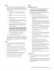
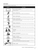
SafetySymbols This page depicts and describes safety symbols that may appear machine before attempting to assemble and operate. on this product. Read, understand, and follow all instructions on the READ THE OPERATOR'S MANUAL(S) Read, understand, assemble and follow all instructions in the manual(s) before attempting to and operate DANGER-- ROTATING BLADES Never carry passengers. Never carry children, even with the blades off.
co or a corner of a building... I I -4 6 Z | I ,_ I i i | Z ' FOldo,_ O ' ' or a fence post ', " .- 22 diine 6 .I Z ' "o a 15Oslope -4 I I 15 ° Usethis page as a guide to determine slopeswhere you may not operate safely. WARNING! Do not operate (a rise of approximately mowers up and down your lawn mower on such slopes. Do not mow on inclines 2-1/2 feet every 10 feet). A riding mower slopes, never across the face of slopes.
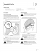
3 Assembly & Set-Up Contents of Crate One Lawn Tractor One Oil Drain Tube One Lawn Tractor Operator's Manual One DeckWash One Kohler Engine Operator's Manual Shipping BraceRemoval TractorSet-Up Moving TheTractor Manually Your tractor's transmission relief valve for occasions tractor manually. is equipped with a hydrostatic off, set the parking brake and remove the ignition WARNING! Make sure lawn tractor's key before removing thethe shipping brace.
CheckingTire Pressure Connecting the Battery Cables CALiFORNiA PROPOSiTiON 65 WARNING: Battery posts, terminals, and related accessories contain lead and lead compounds, chemicals known to the State of California to cause cancer and reproductive harm. Wash hands after handling. CAUTION: When attaching battery cables, always the POSITIVE (red) wire to its terminal first, connect followed To connect The tires on your tractor may be over inflated purposes.
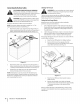
Adjusting the Seat To adjust the position adjustment of the seat, pull up and hold the seat lever. Slide the seat forward or rearward to the desired position; then release the adjustment lever. Make sure seat is locked into position before operating the tractor. See Fig. 3-5. J Figure WARNING! Before operating the seat is engaged parking 3-5 the tractor, in the seat-stop. make sure Engage the brake. Stand behind the machine and pull back on seat until it clicks into place.
4 Controls and Features Systems indicator Monitor Fuel Tank Cap ignition Switch Module Throttle/Choke Control PTO Knob Fuel Level indicator Drive Peda I Cargo Net Pedal Parking Brake/ Deck Lift Lever Seat Adjustment Lever Stora¢ i 1 Holder Figure 4-1 Lawn Tractor controls and features are illustrated described on the following pages. in Fig.
DeckLift Lever SystemsIndicator Monitor/HourMeter LCD Found on your tractor's right fender, the deck lift lever is used to change the height of the cutting deck. To use, move the lever to the left, then place in the notch best suited for your application. Ignition Switch Module leave a running _ @ machine ARNING! unattended. Never Always disengage PTO, set parking brake, stop engine and remove key to prevent starting.
Fuel LevelIndicator The Fuel Level Indicator tractor's tank. is located dash and indicates on the left side of the the amount of fuel in the gas PTO/ BladeEngageKnob Activating the PTO engages PTO power to the cutting deck or other (separately available) attachments. Pull outward on the PTO/Blade Engage knob to activate it. Push the PTO/Blade Engage knob inward to disengage the power to the cutting deck or other (separately available) attachments.
Operation Startingthe Engine TO AVOID SERIOUS INJURY OR DEATH • • • • GOUP ANDDOWNSLOPES,NOTACROSS. AVOIDSUDDENTURNS. DONOTOPERATE THEUNITWHEREIT COULDSLIPORTIP. IF MACHINESTOPSGOINGUPHILL,STOPBLADE(S) ANDBACKDOWNHILLSLOWLY. • KEEPSAFETYDEVICES(GUARDS,SHIELDS,AND SWITCHES,ETC.) IN PLACEANDWORKING. • REMOVE OBJECTS THATCOULD BETHROWN BYTHEBLADE(S). • KNOWLOCATIONANDFUNCTIONOFALLCONTROLS. • BESUREBLADE(S)ANDENGINEARESTOPPEDBEFORE PLACINGHANDSORFEET NEARBLADE(S).
ReverseCaution Mode DrivingTheTractor and sudden WARNING! i_ stops. Avoid sudden The REVERSE CAUTION MODE position of the key switch module allows the tractor to be operated in reverse with the blades (PTO) starts, excessive speed engaged. NOTE: Mowing 1. Lightly press the brake pedal to release the parking brake. Move the throttle lever into the FAST(rabbit) position. 2. To travel FORWARD,slowly press the upper portion of the drive pedal forward until the desired speed is achieved. See Fig. 5-1.
CruiseControl Driving OnSlopes Refer to the SLOPE GAUGE on page 8 to help determine where you may operate the tractor slopes while traveling in reverse. ARNING! Never engage safely. _ i_ll excess of 15 degrees (a rise of approximately 2-1/2 WARNING! notThe mow on inclines with a slope feet every 10 Do feet). tractor could overturn and in To set the cruise control: cause serious injury. 1. Mow up and down Exercise extreme when changing direction 2. on Lightly slopes.
2. Pull the PTO/Blade Engage knob outward (ON) position. into the engaged See Fig. 5-3. OFF Figure 5-3 NOTE: Always operate the tractor FAST (rabbit) position for the most efficient deck or other (separately available) with the throttle lever in the use of the cutting attachments. Mowing WARNING! To help avoid blade contact or a thrown object injury, keep bystanders, helpers, children and pets at least 75 feet from the machine while it is in operation. enters the area.
6 Maintenance & Adjustments MaintenanceSchedule Before Every Every Every Every Eachuse 10 Hours 25 Hours 50 Hours 100 Hours CleanHood/DashLouvers M/ CheckAir Filterfor Dirty,Looseor DamagedParts _" CleanandRe-oilAir Filter'sFoamPrecleaner to Storing ,/ M/ CheckEngineOil Level Prior _/ ReplaceAir Filter Element M/ ChangeEngineOiland ReplaceOil Filter M/ CleanBattery Terminals _/ _/ LubeFrontAxlesand Rims _/ _/ CleanEngineCoolingFins M/ M/ LubeFrontDeckWheels _/ _/ LubeDec
3. Pop open the protective cap on the end of the oil drain Hydrostatic Transmission valve to expose the drain port. See Fig 6-1. The hydrostatic transmission maintenance-free. The fluid fluid cannot is sealed at the factory and is level cannot be checked and the be changed. Battery Battery posts, terminals, and related accessories CALIFORNIA WARNING! contain lead andPROPOSITION lead compounds, 65chemicals known to the State of California reproductive to cause cancer and harm.
4. Attach the hose coupler surface. See Fig. 6-2. Lubrication to the water port on your decks _L inspecting, always disengage PTO, set parking ARNING! Before and lubricating, repairing, or brake, stop engine remove key to prevent unintended starting. FrontWheels Each of the front wheel axles and rims is equipped grease fitting. grease applied See Fig. 6-3. Lubricate with a with a No. 2 multi-purpose with a grease gun after every 25 hours of tractor operation. / / k. j Figure 6=2 5.
Determine DeckSpindle Grease fittings Lubricate can be found on each deck spindle. See Fig. 6-4. with 251H EP grease or an equivalent adjustment and )roceed, Loosen (thread No. 2 multi- purpose lithium grease. Using a grease gun, apply two strokes (minimum) or sufficient grease to the spindle shaft. the approximate deck hanger distance necessary for proper if necessary. outward) the hex lock nut on the end of the rod. See Fig. 6-5. r / /i ............................. "................
Leveling the Deck(Sideto Side) If the cutting adjustment 1. Steering Adjustment deck appears to be mowing can be performed. Adjust unevenly, a side to side if necessary Measure the distance from the outside tip to the ground and the distance right blade tip to the ground. should 3. be equal. If they're Loosen, with the tractor.
7 Service NOTE: If there Cutting DeckRemoval To remove the cutting 1. easily removed deck, proceed as follows: Place the PTO/Blade Engage knob in the disengaged }osition the parking and engage is too much tension from the electric on the belt for it to be PTO clutch, carefully insert a %" drive ratchet wrench (set to tighten) into the square hole found in the left-hand deck idler bracket and pivot it (OFF) toward brake. the tractor's right side to relieve tension on the belt. See Fig.
6. Pullthedecksupport pinoutward torelease thedeck from Cutting fllades the deck lift arm. See Fig. 7-3. WARNING! ignition Shut the engine off and remove key before removing the cutting blade(s) for sharpening or replacement. Protect your hands by using heavy gloves when grasping the blade. spindle for cracks or damage, especially after you've WARNING! the blade and/or struck a foreignPeriodically object. Doinspect not operate the machine until damaged components are replaced.
4. To properly amounts cutting sharpen the cutting of metal from edges, parallel blades, remove equal both ends of the blades along the to the trailing Battery CALIFORNIA edge, at a 25 ° to 30 ° angle. Always grind each cutting blade edge equally maintain proper blade balance. See Fig. 7-6. to PROPOSiTiON 65 WARNING: Battery posts, terminals, and related accessories contain lead and lead compounds, chemicals known to the State of California to cause cancer and reproductive harm.
Fuse Changingthe DeckBelt WARNING! inspecting, always disengage PTO, set parking WARNING! Before and servicing, or brake, stop engine remove repairing, key to prevent unintended starting. ill&i A fuse is installed in your tractor's tractor's system from electrical wiring harness to protect damage ignition Shut the engine off and remove key before removing the cutting blade(s) for sharpening or replacement. Protect your hands by using heavy gloves when grasping blades and pulleys.
5. To place the new belt begin by routing the belt around two outer spindle the front spindle pulleys, then around the pulley as shown in Fig. 7-8. f Outer Spindle Pulleys Figure 7-8 6. Route the belt around the two deck idler pulleys as shown in Fig. 7-8. 7. Retighten the belt keeper rod loosened 8. Remount the belt guards removed 9. Re-install around 10. the deck making earlier. earlier. sure the belt remains routed the pulleys as instructed.
Troubleshooting Problem Engine fails to start Cause Remedy 1° PTO/Blade Engage knob engaged. 1. Place knob in disengaged 2. Parking brake notengaged. 2. Engage parking 3. Spark plug wire(s) disconnected. 3. Connect wire(s) to spark plug(s). 4. Throttle 4. Place throttle control lever not in correct starting (OFF) position. brake. lever to FAST position. position. S. Choke not activated 5. Push the Throttle/Choke control into the CHOKE position. Engine runs erratic 6.
9 ReplacementParts 1- _ Component Phone (800) 965-4CUB ready). Parts Manual to order replacement downloads parts or a complete are also available Part Number and Description 759-3336 Spark Plug KH-32-883-03-$1 Air Filter and Pre-cleaner KH-12-050-01-S Oil Filter KH-25-050-22-$1 Fuel Filter 954-0642 Deck Drive Belt 942-0677B 2-in-1 Deck Blade 918-04126B Deck Spindle 734-04155 Deck Wheel Parts Manual (have your full model number free of charge at www.cubcadet.
Component l 0 ? Phone (800) 965-4CUB ready).
1 Attachments & Accessories The following attachments or the retailer from which you purchased i_ attachments CAUTION: and accessories are compatible your tractor for Cub Cadet SLTX1054. Call (800) 965-4CUB for information regarding or see your Cub Cadet dealer price and availability. (e.g. tiller or moldboard plow). Use of this type of equipment WILL void the tractor's warranty.
11 33
FEDERAL and/or CALIFORNIA EMISSION CONTROL WARRANTY STATEMENT YOUR WARRANTY RIGHTS AND OBLIGATIONS MTDConsumerGroupInc,the United StatesEnvironmentalProtectionAgency (EPA),and, forthose productscertifiedfor sale in the stateof California,the CaliforniaAir ResourcesBoard(CARB)are pleasedto explainthe emission(evaporativeand/or exhaust)controlsystem(ECS) warrantyon youroutdoor 2006 andlater smalloff-roadspark-ignitedengine andequipment(outdoorequipmentengine)In California,new outdoorequipmentengines must
WARRANTED PARTS: The repairor replacementof any warrantedpart otherwiseeligiblefor warrantycoveragemay be excludedfrom such warrantycoverageif MTDConsumerGroup Inc demonstratesthatthe outdoor equipmentengine has beenabused,neglected,or improperlymaintained,and thatsuch abuse, neglect,or impropermaintenancewasthe direct causeof the needfor repairor replacementof the part.
CUB CADET LLC MANUFACTURER'S LiMiTED WARRANTY FOR SERIES 1000 & SERIES 1500 TRACTORS IMPORTANT: To obtain warranty coverage owner must present an original proof of purchase and applicable maintenance records to the servicing dealer. Please see the operator's manual for information on required maintenance and service intervals. In the U.S.A.: Check your Yellow Pages, or contact Cub Cadet LLC at P.O.Box 361131, Cleveland, Ohio 44136-0019, call 1-877-282- 8684 or log on to our website at www.cubcadet.com.
Medidas importantes de seguridad • Configuraci6n • Funcionamiento ANUAL • Mantenimiento • Servicio • Soluci6n de problemas • Garantia EL OPE Tractor Corta C_specl Hiclrost_tico m SLTX1054 CUB CADET LLC, P.O. BOX 361131 CLEVELAND, OHiO 44136-0019 Impresoen EstadosUnidosdeAmerica FormularioNo.
1 A!propietario Gracias Gracias por comprar una Cub Cadet tractor corta c_sped. El mismo ha sido dise_ado cuidadosamente para brindar excelente rendimiento si se Io opera y mantiene correctamente. Por favor lea todo este manual antes de operar el equipo. Le indica c6mo configurar, operar y mantener la m&quina con seguridad y f_cilmente. Pot favor asegOrese de seguir cuidadosamente yen todo momento las pr_cticas de seguridad recomendadas y de hac&rselas seguir a cualquier otra persona que opere la m_quina.
2 Medidasimportantesde seguridad ADVERTENCIA" importantes personal La presencia de seguridad y/o material de este s[mbolo que se deben provocar lesiones personales. ADVERTENCIAS! algunos problemas Lea y siga todas las instrucciones Cuando considera su seguridad de este manual Si no respeta estas instrucciones vea este s[mbolo, puede iTENGA EN CUENTAS LAS 65 DE CALIFORNIA El escape del motor de este producto, componentes de California para evitar poner en peligro esta m_quina.
10. Est_ atento alacortadora yaladirecci6n deladescarga 28. Losdatos estadisticos muestran quelosoperadores de60 delosaditamentos ynoapunte anadie. Nunca operela ahos y mayores seven involucrados enunaltoporcentaje cortadora dec_sped sinqueest_n ensulugarapropiado la delesiones relacionadas contractores cortac_sped. Estos cubierta dedescarga oelcolector derecortes dec_sped. operadores deben evaluar sucapacidad para operar el tractor corta c _sped enforma s uficientemente segura para 11.
6. No cambie a transmisidn neutral para descender. El exceso de velocidad puede hacer que el operador pierda el control de la m_quina, ocasionando lesiones graves e incluso la muerte. 7. No remolque cargas pesadas detr&s de los aditamentos (carrito de basura cargado, podadora de rodillos, etc) en Servicio Manej0 segur0 de la gas01ina: 1. pendientes mayores de 5 grados.
2. 3. 4. 15. Antes de limpiar, reparar o inspeccionar la m_iquina, compruebe que la(s) cuchilla(s) y todas las partes en movimiento se hayan detenido. Desconecte el cable de la bujia y p6ngalo haciendo masa contra el motor para evitar que se encienda accidentalmente.
SafetySymbols This page depicts and describes safety symbols that may appear machine before attempting to assemble and operate. on this product. Read, understand, and follow all instructions on the LEA EL MANUAL(S) DEL OPERADOR leido, entienda, funcionar PELIGRO-- y siga todas las instrucciones en el manual(s) antes de procurar montar y DIe EL CORTE DE PIE Nunca transporte pasajeros. Nunca transporte nifios, aun con la cuchilla apagada.
I,Z 2 I ¢N Z o I- ! | 15 ° Useesta p_gina como gu_apara determinar ADVERTENCIA: (elevaci6n No opere la cortadora aproximada las pendientes en qu_ pendientes no puede operar el tractor de manera segura. de c6sped en dichas pendientes. de 2 I/2 pies por cada 10 pies). El tractor opere con los tractores corta-c_sped No corte en inclinaciones corta c_sped podria voltearse mayores de 15 grados y causar lesiones graves. En hacia arriba y abajo, nunca de forrna transversal.
3 Montajey Configuraci6n Contenido dei caj6n Un tractor corta c6sped Un tubo de drenaje Un acoplador de aceite de manguera para lavado de plataforma Un Manual del operador del tractor Un Manual Kohler corta c_sped del operador Extracci6n de la traba de seguridad utilizada en el envi0 Configuraci6n dei tractor Mover Manualmente el Tractor Su transmisi6n del tractor del motor tractor est_ equipado con una v_lvula corta c_sped traba de seguridad escape para ocasiones en que es necesari
Instalad6n del cablede la batedas PROPUESTA 6S DE CALIFORNIA ADVERTENCIA! terminales neum_ticos en cualquier circunstancia es de 30 psi. IADVERTENCIA! La presi6n los todos Se debe mantener una presi6n m_xima uniformede para los neum_ticos en todo momento. Los postes de la bateria, y accesorios plomo y compuestos relacionados qu[micos, contienen conocidos por el Estado de California que causan c_ncer y daffos en la reproducci6n.
d. Vuelva a insertar el tornillo cada rueda de calibraci6n) posicionamiento con reborde dentro la secci6n Mantenimiento detalladas Nivelaci6n para obtener 1/2 de la rueda y el de la plataforma de este manual sobre diferentes 6as01inay aceite de que deja aproximadamente pulgada entre la parte inferior pavimento. Consulte (con del orificio en la secci6n instrucciones El tanque de combustible gir_indola en sentido debajo del guardabarros y medio.
4 Controles y Caractefisticas Monitor del indicador de sistemas Tap6n del tanque M6dulo del interruptor de de combustible encendido Control "_ Interruptor de la potencia de arranque (PTO) del regulador/cebador Indicador Pedaldela Pedal de freno Cargo Neto Pedal de la marcha arras Freno de mano / palanca de control Palanca de aj Palanca de elevaci6, de la plataforma de crucero Ahuequea Poseedor Figure 4-1 Los controles y caracteristicas del tractor corta c_sped se ilustran en la Figura
Palancade elevad6n de ia plataforrna Monitordei indicadorde sistemas/ PantaliaLCDdel medidorhoratio Ubicada en el guardabarros derecho de[ plataforma se utiliza para cambiar la altura de la plataforma de corte. Para utilizarla, mueva [a palanca hacia ia izquierda, col6quela en la muesca que mejor adapte a [a aplicaci6n deseada. _ [uego se M6dulo dei interruptorde encendido Nunca deje la _[b © IADVERTENCiA! m_quina en funcionamiento sin I vigilancia.
Bateria (Si el motor equipados) Es normal que la luz de la bateria se ilumine est_ girando durante el arranque, cuando Freno de mano/palanca de control de crucero F el motor pero si se ilumina durante la operaci6n, cuando el motor est_ funcionando, la bateria necesita carga o el sistema de carga del motor no est_ generando amperaje suficiente.
5 Funcionamiento Encendidodel motor NOTA: Consulte PARA EVITAR LESIONES PERSONALES O LA MUERTE EN LAS PENDIENTES PODE HACIA ARRIBAY FORMA TRANSVERSAL. EVITE MANIOBRAS HACIA ABAJO, NO DE DE GIRO BRUSCAS. NO OPERE LA UNIDAD TROPEZAR SI LA MAQUINA GRAVES EN AREAS DONDE PUEDE DERRAPAR DEJA DE SUBIR LA PENDIENTE, DETENGA LA(S) (PROTECCIONES, ESCUDOS, INTERRUPTORES, EN CORRECTO FUNCIONAMIENTO. RETIRE LOS OBJETOS QUE PUEDAN CUCHILLA(S). CONOZCA LA UBICACI6N Y FUNCI6N DE TODOS POR LA(S) 3.
Conducci6ndei tractor opere el tractor en MODO DE PRECAUCION EN ADVERTENCIA! Tenga muchohacia cuidado MARCHA ATRAS. Mire siempre abajo cuando y hacia _ desarrollar excesiva velocidad y detenerse de ADVERTENCIA! Evite arrancar subitamente, repente. _I_ 1. Presione levemente el pedal del freno Para conducir superior hacia adelante, presione del pedal de transmisi6n se alcance la velocidad \ el tractor Para utilizar a la posici6n pot una liebre).
IADVERTENClA! Nocorteelc6sped en Corte de c sped inclinaciones mayores a15grados (elevaci6n IADVERTENCIA! Para tratar de evitar el contacto aproximada de2-1/2 piescada10pies). Eltractor podria voltearse ycausar lesiones severas. con las cuchillas o una lesi6n pot alg0n objeto que sea arrojado, mantenga a los observadores, a los Enlaspendientes cortehacia arriba y hacia ayudantes, niffos y mascotas alejados al menos 25 abajo, NUNCA enforma transversal.
Colocaci6n dei freno de rnano/ Activaci6ndel controlde crucero Activad6ndel controldecrucero NOTA: El aparcamiento romper y control de crucero est_in controladas pot la misma palanca. Si se utiliza el freno, cuando _ control de crucero atr_is. ADVERTENCIA! Para colocar el control el freno de mano / palanca de control de crucero el freno mano participate1. Si se utiliza la unidad de mano/palanca entablar_i. de crucero el control de control de de pedal, cuando el freno de crucero 1. 2.
6 Mantenimientoy Ajustes Calendario de mantenimiento Antes decadauso Cada 25 horas Cada 10 horas Cada 50horas Cada 100horas Antes de almacenar ,/ Limpie el cap611osrespiraderos Inspecdone el nivel de aceite del motor y / Controle el flltro de aire para vet si hay piezas sucias, sueltas o da5adas M/ ,/ Limpie y vuelva a lubricar el depurador de espuma del filtro de aire M/ Reemplace el elemento del flltro de aire y / Cambie el aceite del motor y reemplace el flltro de aceite M/ Limpie los
2. Abra el cap6 del tractor y ubique el puerto aceite del lado izquierdo de drenaje de 8. del motor. Vea la Fig. 6-1. Cuando termine de drenar el aceite, empuje el extremo la v_lvula de drenaje de aceite hacia adentro, lengOetas calcen en su lugar. Vuelva a tapar el extremo la v_lvula de drenaje para evitar que entren orificio de drenaje. 9. \\ Cambie el filtro Manual 10. del Propietario el volumen del Kohler.
Smart Jet 10. TM La plataforma de su tractor agua sobre su superficie est_ equipada con un puerto para apagar el motor de como parte del sistema de lavado de la 11. plataforma. Utilice el Smart Jet TM para lavar la parte inferior Gire la Ilave de encendido Desconecte el agua y retire el acoplador de la manguera desde el puerto de agua que se encuentra en la superficie Despu6s de limpiar funcionamiento 2. agua al alcance de la manguera Lubrkad6n del jardin.
Determine Husillode plataforma Los accesorios de engrase se pueden de la plataforma. encontrar Vea la Figura 6-4. Lubrique adecuado en cada husillo con grasa 251H EP o 1. con una grasa de litio multiuso No. 2 equivalente. Con una pistola de engrasar, haga dos aplicaciones (minimo) o suficiente grasa al la distancia aproximada y, de set necesario, necesaria para un ajuste proceda.
IADVERTENClA! Nivelad6n de la plataforma (lado a lado) Si la plataforma de forma despareja, necesario, 1. de corte estuviera puede realizarse detr_s de la m_quina manera: en la muesca superior (posici6n Mida la distancia m_s alta) y rote ambas izquierda de la punta obtenidas realice el siguiente derecha y tire del asiento hacia atr_s clic.
7 Servkio Extracci6nde ia plataforrnade torte NOTA:Si hay demasiada Para extraer manera: cuidadosamente" la plataforma Coloque la perilla de la potencia (enganche coloque de corte, proceda de cuchilla) de la siguiente de arranque en la posici6n quitada hacia el derecho y Baje la plataforma colocando la palanca de elevaci6n de la )lataforma dentro de la muesca inferior en el guardabarros derecho. 3.
5. Tire hacia afuera el pasador de soporte plataforma. CuchUlas de torte de la plataforma para separar la misma del brazo de elevaci6n de la Vea la Fig. 7-3. Ilave de contacto antes de retirar las cuchillas de ADVERTENCIA! Apague el motor y extraiga la corte para afilado o reemplazo. Proteja sus manos utilizando guantes reforzados cuando maneje las cuchillas.
4. Para afilar las cuchillas extraiga cantidades de corte de forma adecuada, Bateria iguales de metal de ambos extremos IADVERTENClA de las cuchillas a Io largo de los bordes cortantes, de forma paralela al borde de caida, a un _ngulo de 25 ° a 30 °. Afile siempre cada borde de las cuchillas pareja para mantener de corte de forma un equilibrio adecuado PROPOSICION CALIFORNIA! accesorios afines contienen plomo, sustancias quimicas entre las mismas. Vea la Fig. 7-6.
2. Si el cargador de su bateria es autom_itico, hasta que el cargador carga. Si el cargador horas como minimo. indique cargue la bateria que se ha completado no es autom_itico, cargue la Cambiede ia cerrea de ia plataforma por ocho IADVERTENCIA! Ilave de contacto Apague el motor y extraiga la antes de retirar las cuchillas de corte para afilado o reemplazo. Proteja sus manos utilizando guantes reforzados cuando maneje las IADVERTENCIA! mantenimiento, desconecte cuchillas y las poleas.
Para colocar 5. [a nueva correa comJence la correa alrededor encamJnando de las dos poleas de huso externas, entonces alrededor de la polea de huso delantera indicaciones de Fig. 7-8. Cubierta polea segun las Frente polea del husillo de la poleas L_/A Exterior del husillo poleas ,, j Figura 7-8 6. Entonces encamine la correa alrededor m_s ociosas de la cubierta 7. Vuelva a apretar 8. Remonte a los protectores 9. Reinstale al protector la cubierta correa encaminados instrucciones.
Soluci6nde Problemas Problem El motor funciona manera err_tica Cause de Remedy La unidad est_ funcionando cebador activado. con el regulador/ 1. Presione el control del regulador/cebador. 2. Los cables de la bujia est_n flojos. 2. 3. La linea del combustible 3. Limpie la linea de combustible; combustible se ha echado est_ tapada o el a perder. Conecte y ajuste los cables de la bujia. dep6sito reemplace 4. el filtro de combustible. La ventilaci6n de la tapa del combustible est_ obstruida.
Problem El motor vacila a altas Cause 1. La separaci6n Remedy de la bujia es muy peque_a. 1. Retire la bujia y reajuste la separaci6n. revoluciones Vibraci6n excesiva Corte desigual 1. Cuchilla de corte floja o descentrada. 1. Apriete 2. Cuchilla daflada 2. Reemplace 1. La plataforma nivelada. o curvada. no est_ correctamente 2. La cuchilla de la cortadora 3. Presi6n de neum_ticos SECCION 8-- SOLUCION DE PROBLEMAS no est_ afilada. desigual. la cuchilla y el husillo. la cuchilla. 1.
9 Piezasde reemplazo 1- Componente Llame por tel_fono al (800) 965-4CUB numero y numero de modelo de Repuesto para solicitar _ N_mero de pieza y Descripci6n 759-3336 Bujia KH-32-883-03-$1 Limpiador Pre-Filtro KH-12-050-01-S Filtro deAceite KH-25-050-22-$1 Filtro de CombustibLe 954-0642 Correa de Tracci6n (Plataforma Corte) 942-0677B 2-in-1 Cuchilla de Plataforma 918-04126B Husilla de Plataforma piezas de reemplazo o un Manual de serie de su m_iquina a mano). En www.cubcadet.
Componente Llame por tel_fono al (800) 965-4CUB numero y numero de modelo de Repuesto para solicitar N_mero PIEZAS DE REEMPLAZO de pieza y Descripci6n 734-04155 Rueda de Plataforma 925-1707D Bateria 751-0603A Tapa del Tanque de Combustible 746-04556 Cable de Control de Regulador/ Cebador 925-2054A Llave de Encendido 631-04070A Asamblea de Canal de Descarga piezas de reemplazo o un Manual de serie de su m_iquina a mano). En www.cubcadet.com sin cargo alguno.
1 Aditamentos y Accesorios Los siguientes compatibilidad, aditamentos acoplamiento i_ y accesorios son compatibles el precio y la disponibilidad (tenet con el SLTX1054. Llame (800) 965-4CUB su numero de modelo completo y numero para la informaci6n con respecto a la de serie). de tierra adjuntos(por ejemplo, caha o arado de vertedera).
DECLARACION FEDERAL y/oDECALIFORNIA SOBRE SUS DERECHOS Y OBLIGACIONES GARANTJAS EN EL CONTROL DE EIVIISIONES EN CUANTO A LA GARANTJA MTDConsumerGroupInc, laAgencia de Protecci6nMedioambientalde los EstadosUnidos(EPA),y para aquellosproductoscertificadosparasu ventaen el estadode California,el Departamentode los Recursosdel Aire de California(CARB)secomplacenen explicarla garanfiaque cubre al sistemade control (ECS)de emisiones(evaporativasy/o de escape)de su equipoy motor(motor de equipos de exteriores)de
8. Durante latotalidad delperiodo degarantia delmotor yequipo para todo terreno arriba mencionado, MTD Consumer Group Incmantendr_ unsuministro depiezas bajo garantia suficiente para satisfacer lademanda esperada detales piezas. 9. Cualquier pieza dereemplazo sepodr_ usar para elcumplimiento delmantenimiento olasreparaciones bajo garantia ysesuministrar_n sincargo para elpropietario. Dicho usonoreducir_ lasobligaciones degarantia deMTD Consumer Group Inc. 10.
GARANTiA LllVIITADA DEL FABRICANTE CUB CADET LLC PARA TRACTORES DE SERIE 1000 Y SERIE 1500 IIVIPORTANTE: Para obtener cobertura de garantia, el propietario debe presentar una evidencia original de ia compra y los registros de mantenimiento correspondientes al centro de servicio t_cnico autorizado dei distribuidor. Consulte ei manual del operador para obtener informaci6n sobre los intervalos de mantenimiento y servicio requeridos.