Operator's Manual SERIES 1000 Hydrostatic Lawn Tractor Models LT1042 LT1045 LT1046 LTI050 IMPORTANT: READ SAFETY RULES AND INSTRUCTIONS CAREFULLY Warning: This unit is equipped with an internal combustion engine and should not be used on or near any unimproved forest-covered, brush-covered or grass-covered land unless the engine's exhaust system is equipped with a spark arrester meeting applicable local or state laws (if any), If a spark arrester is used, it should be maintained in effective working
TABLEOFCONTENTS Content Important Safe Operation Practices Slope Gauge Tractor Set-up Know Your Lawn Tractor Operating Your Lawn Tractor Making Adjustments Maintaining Your Lawn Tractor Service Page 3 7 8 9 12 17 19 25 Content Off-season Storage Maintenance Schedule Page 30 30 Maintenance Log Troubleshooting Attachments & Accessories 31 32 33 Specifications Replacement Parts Warranty Information 35 34 37 FINDINGMODELNUMBER This Operator's Manual is an important part of your new lawn tractor.
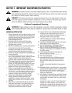
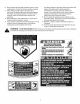
SECTION1: IMPORTANT SAFEOPERATION PRACTICES WARNING: This symbol points out important safety instructions which, if not followed, could endanger the personal safety and/or property of yourself and others. Read and follow all instructions in this manual before attempting to operate this machine. Failure to comply with these instructions may result in personal injury. When you see this symbol--heed its warning.
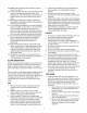
23. Mufflerandenginebecomehotandcancausea burn.Donottouch. 24. Checkoverhead clearances carefullybeforedriving underlowhangingtreebranches,wires,door openingsetc.,wheretheoperatormaybestruckor pulledfromtheunit,whichcouldresultinserious injury. 25. Disengage allattachment clutches,depressthe brakepedalcompletely andshiftintoneutralbefore attempting to startengine. 26. Yourmachineisdesigned tocutnormalresidential grassofa heightnomorethan10".Donotattempt to mowthroughunusually tall,drygrass(e.g.
e. Useextremecarewhenapproaching blind corners,doorways, shrubs,treesor other objectsthatmayblockyourvisionofa child whomayrunintothemachine. f. Toavoidback-overaccidents,always disengagethecuttingblade(s)before shiftinginto reverse.The"Reverse CautionMode" should not be used when children or others are around. Keep children away from hot or running engines. They can suffer burns from a hot muffler. h. Remove key when machine is unattended to prevent unauthorized operation.
8. Nevertamperwiththesafetyinterlocksystemorother safetydevices.Checktheirproperoperationregularly. 9. Afterstrikinga foreignobject,stoptheengine, disconnect thesparkplugwire(s)andgroundagainst theengine.Thoroughly inspectthemachine forany damage.Repairthedamagebeforestartingand operating. 10. Neverattemptto makeadjustments or repairstothe machinewhiletheengineisrunning. 11. Grasscatchercomponents andthedischarge coverare subjecttowearanddamagewhichcouldexpose movingpartsorallowobjectstobethrown.
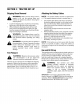
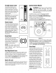
Sight and hold this levelwith a vertical tree... or a corner of a building... i _------ or a fence post | Sonts a 15o ! I.IJ I.IJ Q. 15° &i Z I.
SECTION3: TRACTOR SET-UP ShippingBraceRemoval AttachingtheBatteryCables NOTE: _, engine is off, Make set the brake and WARNING: sure parking the riding mower's remove the ignition key before removing the shipping brace. Locate the shipping brace, if present, and warning tag found on the right side of the cutting deck. While holding the discharge chute with your left hand, remove the shipping brace with your right hand by grasping it between your thumb and index finger and rotating it clockwise.
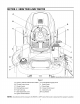
SECTION4: KNOWYOURLAWNTRACTOR A B C H J D F NOTE: Steering Wheel not shown for clarity, Figure I A Systems Indicator Monitor/Hour Meter B Throttle Control Lever H PTO (Blade Engage) Knob I Brake Pedal C Choke Control J D Parking Brake Lever K Cruise Control Lever E FueITank Cap L Deck Lift Lever F Seat Adjustment Lever M Cup Holder Drive Pedal G Ignition Switch Module NOTE: Any reference in this manual to the RIGHT or LEFT side of the tractor is observed from operator's position.
ThrottleControlLever The throttle control lever is located on the left side of the IgnitionSwitchModule Fast Position WARNING: Never leave a running machine unattended. Always disengage PTO, move shift lever into neutral position, set parking brake, stop engine and remove key to prevent unintended starting. tractor's dash panel. This lever controls the speed of the engine. When set in a given position, the throttle will maintain a uniform engine speed.
SystemsIndicatorMonitor/ HourMeter BATT. OIL ElectricPTO/ BladeEngageKnob | To engage the power to the cutting deck or other (separately available) attachments, pull outward on the PTO/Blade .J ......J qlL II Engage knob. Push the PTO/ Blade Engage knob inward to disengage the power to the cutting deck or other (separately available) attachments. 42.0 /// j HOURS 1/10 \\\ / jr 11 NOTE: PTO / BLADE The PTO/Blade Engage knob must be in the disengaged (OFF) position when starting the engine.
SECTION5: OPERATING YOURLAWNTRACTOR WARNING: AVOIDSERIOUS INJURYORDEATH • • • • • • • • GO UP AND DOWN SLOPES, NOT ACROSS. AVOID SUDDEN TURNS. DO NOT OPERATE THE UNIT WHERE IT COULD SLIP OR TIR IF MACHINE STOPS GOING UPHILL, STOP BLADE(S) AND BACK DOWNHILL SLOWLY. DO NOT MOW WHEN CHILDREN OR OTHERS ARE AROUND. NEVER CARRY CHILDREN, EVEN WITH BLADES OFR LOOK DOWN AND BEHIND BEFORE AND WHILE BACKING. KEEP SAFETY DEVICES (GUARDS, SHIELDS, AND SWITCHES) IN PLACE AND WORKING.
• If the gauge wheels have excessive clearance with the surface below, lower the wheels to the index hole that provides the approximate 1/2" clearance as described above. Refer to Levelingthe Deckon page 17 of this manual for more detailed instructions regarding various deck adjustments. SettingtheGaugeWheels Select the height position of the cutting deck by placing the deck lift lever in any of the six different cutting height notches on the right fender.
• EngagingtheParkingBrake To engage the parking brake: • Fully depress the brake pedal and hold it while gently pushing the parking brake lever downward. • Hold the parking brake lever down while removing your foot from the brake pedal. • Once engaged, the parking brake lever and the brake pedal will lock in the "down" position.
Disengage the cruise control using one of the following methods: • • IMPORTANT:Never attempt to move the tractor manually without first opening the hydrostatic relief valve. Doing so will result in serious damage to the tractor's transmission. Depress the brake pedal to disengage the cruise control and stop the tractor. Lightly depress the drive pedal.
• • • • For best results it is recommended that the first two laps be cut with the discharge thrown towards the center. After the first two laps, reverse the direction to throw the discharge to the outside for the balance of cutting. This will give a better appearance to the lawn. Under heavy conditions it may be necessary to go over the cut area a second time to get a clean cut. Do NOT attempt to mow heavy brush and weeds or extremely tall grass. Your tractor is designed to mow lawns, NOT clear brush.
SECTION6: MAKINGADJUSTMENTS • WARNING: Shut the engine off, remove the ignition key and engage the parking brake before making adjustments. Protect your hands by using heavy gloves when handling the blades. • Tighten the inner hex nuts front against the front hanger bracket to raise the front of the deck; loosen the hex nuts to lower the front of the deck. See Figure 10. Retighten the two lock nuts against the inner hex nuts when proper adjustment is achieved.
ParkingBrakeAdjustment If the tractor does not come to a complete stop when the brake pedal is completely depressed, or if the tractor's rear wheels can roll with the parking brake applied (and the hydrostatic relief valve open), the brake is in need of adjustment. See your Cub Cadet dealer to have the brake properly adjusted. SeatAdjustment WARNING: Before operating the tractor, make sure the seat is engaged in the seat stop, stand behind the machine and pull back on seat until fully engaged into stop.
SECTION7: MAINTAININGYOURLAWNTRACTOR NOTE: Refer to MaintenanceCharton page 30 for a reference of recommended maintenance intervals. TEMPERATURE/ OiL ViSCOSiTYCHART ** WARNING: Before performing any maintenance or repairs, disengage PTO, set parking brake, stop engine and remove key to prevent unintended starting.
ChangingtheEngine011 Oil Fill Oap/ Dipstick The engine oil and oil filter should be changed after every 50 hours of tractor operation. WARNING: If the engine has been recently run, the engine, muffler and surrounding metal surfaces will be hot and can cause burns to the skin. Allow the tractor to cool and use caution when removing IMPORTANT:The oil filter should be changed at every oil change interval.
• • Slowly pour oil into the fill tube. Fill the crankcase until the oil level reaches the full (F) mark on the dipstick (Refer to Page 19). Reinstall the oil fill cap/dipstick securely into the oil fill tube. • Paper Element(Single Cylinder Engine) The paper element should be replaced at least once a season, or every 100 hours of operation. Replace more frequently if the tractor is operated under extremely dusty conditions.
Paper Element(Twin Cylinder Engine) The paper element should be replaced at least once a season, or every 100 hours of operation. Replace more frequently if the tractor is operated under extremely dusty conditions. To replace the paper element, proceed as follows: • • • FeelerGauge Spark Plug Pivot the air cleaner cover upward and unhook the wire latch which secures the element in place. Remove the air cleaner element with precleaner.
2. 3. 4. Lubrication Disengage the PTO (Blade Engage), set the parking brake and stop the engine. Thread the hose coupler (packaged with your tractor's Operator's Manual) onto the end of your garden hose. Attach the hose coupler to the water port on your decks surface. See Figure 15. WARNING: Before lubricating, repairing, or inspecting, always disengage PTO, set parking brake, stop engine and remove key to prevent unintended starting.
Carburetor • NOTE: Carburetor adjustments after the engine has warmed up. Make sure fuel is reaching the carburetor. Check the fuel lines and fuel pump for restrictions or faulty components, replace as necessary. • Make sure the air cleaner element is clean and all air cleaner element components are secure. If, after checking the items listed above, the engine is hard to start, runs roughly, or stalls at low idle speed, it may be necessary to adjust or service the carburetor.
SECTION8: SERVICE Tires • • inflation pressureNever shownexceed on the sidewall of the WARNING: the maximum tire. Remove the deck from beneath the tractor, (refer to CuttingDeckRemovalon page 26) then gently flip the deck over to expose its underside. Place a block of wood between the center deck housing baffle and the cutting blade to act as a stabilizer. See Figure 19. The recommended operating tire pressure is approximately 10 psi for the rear tires and 14 psi for the front tires.
IMPORTANT: When charging your tractor's battery, use only a charger designed for 12V lead-acid batteries. Read your battery charger's Owner's Manual prior to charging your tractor's battery. Always follow its instructions and heed its warnings. Battery California Proposition 65 Warning: Battery posts, terminals, and related accessories contain lead and lead compounds, chemicals known to the State of California to cause cancer and reproductive after handling.
ChangingTheTransmission DriveBelt Changingthe DeckBelt NOTE: Several components must be removed and special tools used in order to change the tractor's transmission drive belt. See your Cub Cadet dealer to have your drive belt replaced. ,_ and remove the ignition key,the toengine prevent WARNING: Be sure to shut off unintended starting. WARNING: Avoid the possibility of a pinching injury. Do not place your fingers on the idler spring or between the belt and a pulley while removing the belt.
50-inch Decks • • To ease in removing the belt in later steps, loosen, but do not remove, the bolt which secures the pivoting idler pulley to the idler bracket. See Figure 23. • • Pivoting Idler Pulley Insert a 3/8"-drive ratchet wrench (set to tighten) into the square hole found in the idler bracket on the left side of the deck's surface. See Figure 23. Grasp the ratchet's handle and pivot it toward the tractor's right side to relieve tension on the belt.
LT1042 LT1045& LT1046 LTI050 29
SECTION9: OFF-SEASON STORAGE Clean and lubricate the tractor as instructed in Section7: To empty the system, run the engine until the tank and system are empty. MAINTAINING YOURLAWNTRACTORon page 19 of this manual before storing for an extended period. WARNING: Allow engine to cool. Extinguish cigarettes, cigars, pipes, and other sources of ignition prior to draining fuel. Drain fuel only into an approved container outdoors, away from an open flame.
SECTION11: MAINTENANCE LOG Please keep a record of the maintenance performed on your tractor.
SECTION12: TROUBLESHOOTING Trouble Possible Engine fails to start PTO/Blade Engage knob engaged. Parking brake not engaged. Spark plug wire(s) disconnected. Throttle control lever not in correct starting position. Choke not activated Fuel tank empty, or stale fuel. Blocked fuel line. Faulty spark plug. Engine flooded. Unit running with CHOKE activated. Spark plug wire(s) loose. Blocked fuel line or stale fuel. Engine runs erratic Corrective Cause(s) Vent in gas cap plugged.
SECTION13: ATTACHMENTS & ACCESSORIES The following attachments and accessories are compatible for Series 1000 Lawn Tractors. See your Cub Cadet dealer or the retailer from which you purchased your tractor for information regarding price and availability. NOTE: Cub Cadet Series 1000 lawn tractors are NOT designed for use with any type of ground-engaging attachments (e.g. tiller or moldboard plow). Use of this type of equipment WILL void the tractor's warranty.
SECTION14: REPLACEMENT PARTS NOTE: Phone (800) 965-4CUB to order replacement parts or a complete Parts Manual (have your full model number and serial number ready). Parts Manual downloads are also available free of charge at www.cubcadet.com. LT1042 LT1045 IT1046 IT1050 Spark Plug (Champion RC12YC) 759-3336 759-3336 759-3336 (Qty. 2) 759-3336 (Qty.
SECTION15: SPECIFICATIONS* LT1042 LT1045 LT1046 LTI050 Fuel Tank 3.5 gal. (13.2 liters) 3.5 gal. (13.2 liters) 3.5 gal. (13.2 liters) 3.5 gal. (13.2 liters) Engine Crankcase (w/filter) 50.75 oz. (1.5 liters) 50.75 oz. (1.5 liters) 57.5 oz. (1.7 liters) 57.5 oz. (1.7 liters) Transmission 76 oz. (2.25 liters) 76 oz. (2.25 liters) 76 oz. (2.25 liters) 76 oz. (2.
CALIFORNIA EMISSION CONTROL WARRANTY STATEMENT YOUR WARRANTY RIGHTS AND OBLIGATIONS TheCaliforniaAir ResourcesBoardand MTDConsumerGroupInc.are pleasedto explainthe evaporativeemissioncontrolsystemwarrantyon your2007lawnmower. In California,new lawnmowermustbe designed,builtandequippedto meetthe State'sstringentanti-smogstandards.MTDConsumerGroupInc. mustwarrantthe EECSon yourlawn mowerforthe periodof time listedbelowprovidedtherehas been no abuse,neglector impropermaintenanceof yourlawnmower.
FEDERAL AND KOHLER CO. CALIFORNIA EMISSION CONTROL SYSTEMS LIMITED WARRANTY UTILITY AND LAWN AND GARDEN ENGINES The U.S. Environmental Protection Agency (EPA), the California Air Resources Board (CARB), and Kohler Co. are pleased to explain the Federal and California Emission Control Systems Warranty on your small off-road equipment engine. For California, engines produced in 1995 and later must be designed, built and equipped to meet the state's stringent anti-smog standards.
CUB CADET LLC MANUFACTURER'SLIMITED WARRANTY FOR SERIES 1000 & SERIES 1500 TRACTORS IMPORTANT:Toobtainwarrantycoverageownermustpresentan original proofof purchaseandapplicablemaintenancerecordsto the servicingdealer. Pleaseseethe operator'smanualforinformationon requiredmaintenanceand serviceintervals.
CUBCADET LLC, P.O.