Safe Operation Practices • Set-Up • Operation • Maintenance • Service • Troubleshooting • Warranty Operator’s Manual Electric Mower — CC 500 EL WARNING READ AND FOLLOW ALL SAFETY RULES AND INSTRUCTIONS IN THIS MANUAL BEFORE ATTEMPTING TO OPERATE THIS MACHINE. FAILURE TO COMPLY WITH THESE INSTRUCTIONS MAY RESULT IN PERSONAL INJURY. CUB CADET LLC, P.O. BOX 361131 CLEVELAND, OHIO 44136-0019 Printed In USA Form No.
1 To The Owner Thank You Thank you for purchasing an Electric Mower manufactured by Cub Cadet. It was carefully engineered to provide excellent performance when properly operated and maintained. Please read this entire manual prior to operating the equipment. It instructs you how to safely and easily set up, operate and maintain your machine. Please be sure that you, and any other persons who will operate the machine, carefully follow the recommended safety practices at all times.
Important Safe Operation Practices 2 WARNING: This symbol points out important safety instructions which, if not followed, could endanger the personal safety and/or property of yourself and others. Read and follow all instructions in this manual before attempting to operate this machine. Failure to comply with these instructions may result in personal injury. When you see this symbol, HEED ITS WARNING! DANGER: This machine was built to be operated according to the safe operation practices in this manual.
10. 11. Do not put hands or feet near rotating parts or under cutting deck. Contact with blade can amputate hands and feet. 12. A missing or damaged discharge chute can cause blade contact or thrown object injuries. 13. Many injuries occur as a result of the mower being pulled over the foot during a fall caused by slipping or tripping. Do not hold on to the mower if you are falling; release the handle immediately. 14. Never pull the mower back toward you while you are walking.
33. If situations occur which are not covered in this manual, use care and good judgment. Contact Customer Support for assistance or the name of the nearest service dealer. Service 1. Slopes are a major factor related to slip and fall accidents which can result in severe injury. Operation on slopes requires extra caution. If you feel uneasy on a slope, do not mow it.
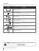
Safety Symbols This page depicts and describes safety symbols that may appear on this product. Read, understand, and follow all instructions on the machine before attempting to assemble and operate. Symbol Description READ THE OPERATOR’S MANUAL(S) Read, understand, and follow all instructions in the manual(s) before attempting to assemble and operate DANGER — ROTATING BLADES To reduce the risk of injury, keep hands and feet away.
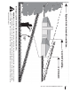
Use this page as a guide to determine slopes where you may not operate safely. WARNING! Do not operate your lawn mower on such slopes. Do not mow on inclines with a slope in excess of 15 degrees (a rise of approximately 2-1/2 feet every 10 feet). A riding mower could overturn and cause serious injury. Operate riding mowers up and down slopes, never across the face of slopes. Operate walk-behind mowers across the face of slopes, never up and down slopes.
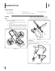
3 Assembly & Set-Up Contents of Carton • One Lawn Mower • One Grass Catcher • One Cord Guide Bar • One Lawn Mower Operator’s Manual Assembly 2. Handle 1. • One Side Discharge Chute Tighten star knobs securing lower handle to handle brackets. See Fig. 3-2. Make certain the lower handle is seated securely into the handle mounting brackets. Remove any packing material which may be between upper and lower handles. a. Loosen each hand knob found on the inside of the upper handle. b.
NOTE: Do not plug your extension cord into the power source receptacle (outlet) prior to routing it through the cord retainer and connecting the extension cord to the mower’s cord outlet receptacle. To properly route your extension cord through the cord retainer: 1. Approximately 14- to 16-inches from its end, crease your extension cord to form a tight loop. 2. Push the loop through the bottom hole in the cord retainer. See Fig. 3-4A. 3.
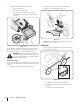
2. Follow steps below to attach grass catcher: a. Lift rear discharge door. b. Remove rear mulching baffle. c. Place grass catcher on the pivot rod. Let go of discharge door so that it rests on the grass catcher. See Fig. 3-6. 2. Slide chute hooks under hinge pin on mulching plug assembly. Lower mulching plug. See Fig. 3-7. 1 2 Figure 3-7 NOTE: Do not remove side mulching plug at any time, even when you are not mulching. Figure 3-6 To remove grass catcher, lift rear discharge door on the mower.
4 Controls and Features Motor/Blade Control Handle Cord Restraint Overload Protection Switch Cutting Height Adjustment Lever Figure 4-1 Motor/Blade Control Handle Cord Restraint The motor/blade control handle is located on the upper handle of the mower. See Figure 4-1. The motor/blade control handle engages and disengages the motor and blade.
5 Operation Starting Motor 2. WARNING: Avoid accidental starting. Make sure Stand behind the mower, in the operating position, depress the (red) starter button and hold it in. See Fig. 5-2. you are in the operating position behind the mower when using it. To avoid serious injury, the operator and unit should be in a stable position while starting. 2 Connecting to an Electrical Power Source WARNING: This mower should be operated on a 15 or 20 AMP circuit.
Stopping the Motor WARNING: The blade continues to rotate for a few seconds after the motor is shut off. If motor does not come to a stop when the motor/blade control handle is released, contact an authorized service dealer. 1. Release the blade/motor control handle to stop the motor and blade. Using Your Lawn Mower Using as Mulcher For mulching grass, remove the grass catcher or side discharge chute from the mower. For effective mulching, do not cut wet grass.
6 Maintenance & Adjustments Maintenance Deck Care WARNING: To reduce the risk of electric shock, do General Recommendations not expose the mower to water. • Always observe safety rules when performing any maintenance. • The warranty on this lawn mower does not cover items that have been subjected to operator abuse or negligence. To receive full value from warranty, operator must maintain the lawn mower as instructed here.
If the overload protection switch pops out shortly after resetting: 1. Release the motor/blade control handle and do NOT restart the mower for at least 15 minutes to allow the electric motor extra time to cool. 2. Press the overload protection switch inward to reset. 3. Restart unit. NOTE: If the overload protection switch pops out repeatedly during operation or will not remain in when attempting to reset, contact your Authorized Service Center to arrange for repair.
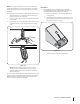
7 Service Blade Care Blade Sharpening WARNING: When removing the cutting blade for sharpening or replacement, protect your hands with a pair of heavy gloves or use a heavy rag to hold the blade. Be certain to disconnect the power supply. To properly sharpen the cutting blades, remove equal amounts of metal from both ends of the blades along the cutting edges, parallel to the trailing edge, at a 25° to 30° angle. See Fig. 7-2.
Blade Installation 1. Place the cutting blade, locking plate, and blade bolt on the motor shaft and thread the blade bolt in finger tight. Refer to Fig. 7-1. NOTE: Make certain to replace the parts in the exact order in which they were removed. When installing the cutting blade, be sure it is installed with the curved ends pointing towards the mower deck and not towards the ground. 2. Torque the blade bolt down using a torque wrench to assure the bolt is tightened properly.
8 Troubleshooting Problem Mower fails to start Remedy 1. Cord disconnected from the motor/blade control. 1. Reconnect the cord keeping the cord restraint close to the motor/blade control. 2. Motor/blade control defective. 2. Replace motor/blade control. 3. Extension cord not connected to the plug on the mower. 3. Connect the extension cord to the plug on the mower. 4. Extension cord not connected to a source of power. 4. Connect the extension cord to a 110-120 volt 60 hertz A.C. receptacle. 5.
9 Replacement Parts Component Part Number and Description 925-04035 Switch Assembly 924-04010 Motor, 120V 764-04055A Grass Bag 731-04177 Side Discharge Chute 634-04346 634-04347 Front Wheel Rear Wheel 942-04152 Blade Contact your Cub Cadet dealer to order replacement parts or a complete Parts Manual (have your full model number and serial number ready). Parts Manual downloads are also available free of charge at www.cubcadet.com.
CUB CADET LLC MANUFACTURER’S LIMITED WARRANTY FOR walk-behind mowerS IMPORTANT: To obtain warranty coverage owner must present an original proof of purchase and applicable maintenance records to the servicing dealer. Please see the operator’s manual for information on required maintenance and service intervals.