
Instructions / Assembly

10 se c t i O n 4 — as s e M b l y & in s t a l l a t i O n
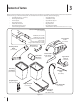
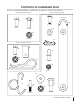
Assembling Remaining Bagger Components
Now that the mounting brackets are assembled and are in place
on the tractor, follow these steps to assemble the remaining
bagger components.
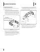
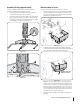
Snap the plastic upper chute support in place by first 1.
clipping the side portion onto the bag support rail with
the edge of the snap feature aligned with the red line (1), as
shown in the inset of Fig. 4-10.
Snap the front portion of the upper chute support to the 2.
bag support rail as seen in 2 of Fig. 4-10.
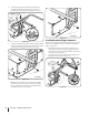
Install the bag support assembly onto the mounting 4.
assembly on the tractor by hooking it over the cross
mounting bracket outside of the two tabs. See Fig. 4-7.
Secure the bag support assembly to the mounting assembly 5.
using a hex bolt (710-3008) and flange lock nut (712-04063)
provided in hardware pack 689-00087. See Fig. 4-8.
Note: On tractors with 42” decks the support assembly
mounts in the center hole as seen above in Fig. 4-8. On
tractors with 46” decks, the support assembly mounts in
the right hand hole as seen in Fig. 4-9.
Tabs
Top View
42” Decks
1
2
46” Decks
Figure 4-7
Figure 4-8
Figure 4-10
Figure 4-9