
Product Manual


6
ENGLISH
Figure 5
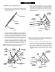
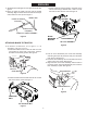
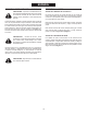
11. Assemble the handle grip onto the upper lift handle. See
gure5.
12. Place the upper lift handle onto the lower lift handle
assembly. Align the holes and secure with the clevis pin
andasmallhaircotterpin.Seegure5.
ATTACHING BLADE TO TRACTOR
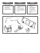
13. To install the shoulder bolts, choose gure 6, 7 or 8,
depending on the type of tractor.
a.Installashoulderboltanda3/8"hexlocknutinthe
frontbracket oneach side of the tractor, unless a
shoulderboltisalreadypresent.Seegure6.
3/8" HEX
LOCK NUT
SHOULDER BOLT
Figure 6
b.Installashoulderboltanda3/8"hexlocknutoneach
sideofthetractorframe.Seegure7.
Figure 7
CLEVIS PIN
UPPER LIFT HANDLE
LOWER LIFT HANDLE ASSEMBLY
HAIR COTTER
PIN (SMALL)
HANDLE GRIP
Figure 9
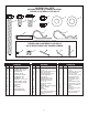
c. Attach a blade mounting bracket to each side of the
tractorframeusingashoulderbolt,a3/8"x3/4"hex
boltandtwo3/8"hexlocknuts.Seegure8.
SHOULDER BOLT
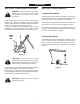
ATTACHMENT PIN
SHOULDER
BOLT
3/8" HEX LOCK NUT
SHOULDER BOLT
3/8" HEX
LOCK NUT
3/8" x 3/4" HEX BOLT
BLADE
MOUNTING
BRACKET
14. Pull out on the attachment pins on the hitch assembly
and swing the top of the pins down away from the holes
theywerein.Seegure9.
15. Hook the hitch assembly onto the shoulder bolts in the
sidesofthetractorframe.Seegure9.
16. Align the holes in the hitch assembly with the holes in
the tractor frame. Insert the attachment pins to lock the
hitchassemblyinplace.Seegure9.
Figure 8