Safe Operation Practices • Set-Up • Operation • Maintenance • Service • Troubleshooting • Warranty Operator’s Manual Twin Rear Bagger — Model No. 19A70043100 WARNING READ AND FOLLOW ALL SAFETY RULES AND INSTRUCTIONS IN THIS MANUAL BEFORE ATTEMPTING TO OPERATE THIS MACHINE. FAILURE TO COMPLY WITH THESE INSTRUCTIONS MAY RESULT IN PERSONAL INJURY. CUB CADET LLC, P.O. BOX 361131 CLEVELAND, OHIO 44136-0019 Printed In USA Form No.
1 To The Owner Thank You Thank you for purchasing a Cub Cadet bagging attachment. It was carefully engineered to provide excellent performance when properly operated and maintained. Please read this entire manual prior to operating the equipment. It instructs you how to safely and easily set up, operate and maintain your machine. Please be sure that you, and any other persons who will operate the machine, carefully follow the recommended safety practices at all times.
Important Safe Operation Practices 2 WARNING! This symbol points out important safety instructions which, if not followed, could endanger the personal safety and/or property of yourself and others. Read and follow all instructions in this manual before attempting to operate this machine. Failure to comply with these instructions may result in personal injury. When you see this symbol. HEED ITS WARNING! DANGER! This attachment was built to be used according to the safe operation practices in this manual.
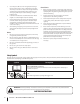
3. Use slow speed. Choose a low enough speed setting so that you will not have to stop or shift while on the slope. Tires may lose traction on slopes even though the brakes are functioning properly. Always keep machine in gear when going down slopes to take advantage of engine braking action. 4. Follow the manufacturer’s recommendations for wheel weights or counterweights to improve stability. 5. Keep all movement on the slopes slow and gradual. Do not make sudden changes in speed or direction.
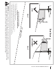
(OK) Figure 1 line Slope Gauge 10° Slope 1 0 ° d a s hed USE THIS SLOPE GAUGE TO DETERMINE IF A SLOPE IS TOO STEEP FOR SAFE OPERATION! To check the slope, proceed as follows: 1. Remove this page and fold along the dashed line. 2. Locate a vertical object on or behind the slope (e.g. a pole, building, fence, tree, etc.) 3. Align either side of the slope gauge with the object (See Figure 1 and Figure 2 ). 4. Adjust gauge up or down until the left corner touches the slope (See Figure 1 and Figure 2). 5.
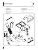
3 Contents of Carton Before beginning installation, remove all parts from the carton to make sure everything is present. Carton contents are listed below and shown in Fig. 3-1. The four hardware packs included in this kit are detailed on this and the following page. • Two Adhesive Foam Strips • Upright Support • Grass Catcher Cover • Chute Discharge Bracket • Chute Tube Extension • Hitch Bracket Kit (5 Pcs.: 2 side & 1 cross mount, 2 wt.
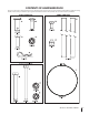
CONTENTS OF HARDWARE PACK This grass collector kit is shipped with three loose hardware packs enclosed and one set of hardware packed with the upright mounting bracket. Please check your hardware packs against the illustrations below. The quantities for each item is listed in parenthesis.
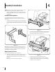
4 Assembly & Installation NOTE: References to left, right, front and rear of the tractor are from the operator’s position, unless otherwise stated. • Before assembly, place the tractor on a firm, level surface, disengage the PTO, stop the tractor engine and set the parking brake. Assemble Mounting Brackets To assemble the bagger mounting assembly, locate the mounting assembly parts, as shown in Figure 4-1, and follow these steps: 1.
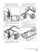
5. Secure the upright support bracket to the mounting assembly in the mounting hole available for the deck size this bagger is being installed on. See Figure 4-4 for the proper mounting location. Use a 710-0376 hex bolt and 712-04063 flange lock nut from hardware pack 689-00320. 7. Snap the plastic upper chute support in place by first clipping the side portion onto the bagger support rail (1) with the edge of the snap feature aligned with the line on the label, as shown in the inset of Figure 4-6.
. Clip in the other side of the screen by flexing the screen and pushing it down into the other corresponding cutout hole. See Figure 4-8. Figure 4-10 Make sure screen sits under the cover’s lip Figure 4-8 11. Install the bagger cover onto the bag support assembly, as seen in Figure 4-9. The plastic cover goes inside of the two mounting tabs. 13.
14. Install both bag assemblies onto the bag support brackets by inserting the front edge in first, as seen in 1 of Figure 4-13, and setting the back edge down until it fits into the assembly (2). 3. Apply a wide adhesive rubber strip, included in hardware pack 689-00342, onto the chute extension tube, approximately 1.25 inches from the narrow end of the extension tube, which should be approximately a quarter inch above the bead on the narrow end of the extension tube, as shown in Figure 4-15.
6. Secure the flexible hose extension to the upper chute assembly using the (726-05019) hose clamp included in hardware pack 689-00342. Installing the Discharge Chute When installing the discharge chute, two different installation instructions exist. For the 54” Fabricated deck units, the discharge chute elbow mounts directly onto the cutting deck. For the 50” and 54” stamped decks, an adapter must first be installed.
5. Secure the discharge chute elbow to the cutting deck using a (720-04122) wing knob included with the bagger kit. Refer to Figure 4-20. 2 1 Figure 4-22 5. Figure 4-20 On 50” and 54” Stamped Decks: 1. Raise the deck to its highest position. 2. Remove the deck pin rubber protective cap, 1 in Figure 4-21. 3.
7. Install the upper chute tube onto the discharge chute elbow as shown in Figure 4-24. Install The Counter Weight The front weight kit is designed for use with all RZT-L (Lap Bar) Residential Zero-turn models. The front weight kit is NOT designed nor required for use with all RZT-S (Steering Wheel) Residential Zero-turn models. WARNING: This front-weight kit is required when operating any compatible lap bar RZT-L models equipped with a grass collector.
2. Attach the weight bar assembly to the front axle with a 3 1⁄4-inch (710-3056) screw and (712-04063) flange nut from hardware pack 689-00325 on the left side. Repeat on the right side. Do not fully tighten at this time. See Figure 4-27. Figure 4-27 3. Visually center the weight bar assembly on the tractor and tighten the hardware installed in step 2 to secure the brackets to the front axle.
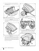
5 Operation Bagger Usage NOTE: When both grass bags are full, place the tractor on a firm, level surface, disengage the PTO, turn the tractor engine off and set the parking brake. 1. Open the grass catcher hood by pushing in on the rear, right-side tab with your right hand, as seen in 1 of Figure 5-1, and lifting the cover with your left hand in the center rear of the bagger cover, 2. 2 1 Figure 5-1 2. Do not remove the chute tube assembly from the tractor. 3.
This page intentionally left blank.
6 Parts List 2 24 23 4 32 20 13 25 21 1 11 8 12 9 5 26 3 10 6 14 15 12 27 30 16 12 7 5 12 29 22 18 17 28 19 17 18 31
Ref. Part Number Description 1. 931-05071 Upper Chute Assembly 2. 931-04292 Twin Bagger Cover 3. 731-06497 Upper Chute Support 4. 731-06504 Bagger Cover Screen 5. 710-0276 Carriage Screw, 5/16-18 x 1.00” 6. 710-0376 Hex Head Screw, 5/16-18 x .75” 7. 911-0310 Clevis Pin, .50” Dia. x .78 Lg. 8. 964-04090A Grass-bag Assembly 9. 683-04461A-0637 Twin Bag Support Assembly 10. 683-04519A-0637 Vertical Support Bracket 11. 711-04988 Cover Hinge Pin 12.
CUB CADET LLC MANUFACTURER’S LIMITED WARRANTY FOR SEPARATELY SOLD ATTACHMENTS AND ACCESSORIES IMPORTANT: To obtain warranty coverage owner may be required to present an original proof of purchase and applicable maintenance records to the servicing dealer. Please see the operator’s manual for information on required maintenance and service intervals.