
Warranty

9Section 4 — ASSembly & inStAllAtion
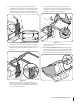
7. Snap the plastic upper chute support in place by first
clipping the side portion onto the bagger support rail (1)
with the edge of the snap feature aligned with the line on
the label, as shown in the inset of Figure 4-6.
1
2
Figure 4-6
8. Snap the front side of the chute support to the rail (2), as
shown in Figure 4-6.
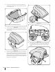
9. If not already installed by the factory, install the bagger
screen into the bagger cover by first inserting one end into
the corresponding cutout mounting hole, as in Figure 4-7.
Make sure to feed the screen under the lip, as in Figure 4-8.
Figure 4-7
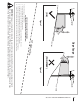
5. Secure the upright support bracket to the mounting
assembly in the mounting hole available for the deck size
this bagger is being installed on. See Figure 4-4 for the
proper mounting location. Use a 710-0376 hex bolt and
712-04063 flange lock nut from hardware pack 689-00320.
54-inch Deck
50-inch Deck
Figure 4-4
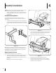
6. Install and secure the hanger assembly onto the upright
support bracket using a 710-0276 carriage bolt and 712-
04063 flange lock nut from hardware pack 689-00320. See
Figure 4-5.
3
Figure 4-5
Note: The carriage bolt (710-0276), from hardware pack
689-00320, goes in the top hole with the nut facing the
engine. The hex bolt (710-0376), from the same hardware
pack, goes in the bottom hole.