Operator’s Manual IMPORTANT: This kit (19A70046100) is required and must first be installed on all ZF-L (Lap Bar) tractors before the 19A70040100 triple bagging kit can be installed. (ZFL) Z-Force L Bagger Mounting Kit 19A70046100 WARNING READ AND FOLLOW ALL SAFETY RULES AND INSTRUCTIONS IN THIS MANUAL BEFORE ATTEMPTING TO OPERATE THIS MACHINE. FAILURE TO COMPLY WITH THESE INSTRUCTIONS MAY RESULT IN PERSONAL INJURY. CUB CADET LLC, P.O. BOX 361131 CLEVELAND, OHIO 44136-0019 Printed In USA Form No.
1 To The Owner Thank You Thank you for purchasing a Cub Cadet bagging attachment. It was carefully engineered to provide excellent performance when properly operated and maintained. in this manual may not be applicable to all models. We reserve the right to change product specifications, designs and equipment without notice and without incurring obligation.
Important Safe Operation Practices 2 WARNING! This symbol points out important safety instructions which, if not followed, could endanger the personal safety and/or property of yourself and others. Read and follow all instructions in this manual before attempting to operate this machine. Failure to comply with these instructions may result in personal injury. When you see this symbol. HEED ITS WARNING! DANGER! This attachment was built to be used according to the safe operation practices in this manual.
3. Use slow speed. Choose a low enough speed setting so that you will not have to stop or shift while on the slope. Tires may lose traction on slopes even though the brakes are functioning properly. Always keep machine in gear when going down slopes to take advantage of engine braking action. 4. Follow the manufacturer’s recommendations for wheel weights or counterweights to improve stability. 5. Keep all movement on the slopes slow and gradual. Do not make sudden changes in speed or direction.
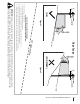
(OK) Figure 1 line Slope Gauge 10° Slope 1 0 ° d a s hed USE THIS SLOPE GAUGE TO DETERMINE IF A SLOPE IS TOO STEEP FOR SAFE OPERATION! To check the slope, proceed as follows: 1. Remove this page and fold along the dashed line. 2. Locate a vertical object on or behind the slope (e.g. a pole, building, fence, tree, etc.) 3. Align either side of the slope gauge with the object (See Figure 1 and Figure 2 ). 4. Adjust gauge up or down until the left corner touches the slope (See Figure 1 and Figure 2). 5.
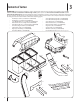
3 Contents of Carton IMPORTANT: Before beginning installation, remove all of the parts from the carton to make sure everything is present. This carton’s contents are listed below with the single astrik (*), three pieces total. The items listed with two asteriks (**) are included in kit 19A70040100. This kit (19A70046100) must be installed first on all ZF-L units before the 19A70040100 triple bagger kit can be installed. This kit includes one (1) hardware pack (689-00343).
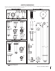
CONTENTS OF HARDWARE PACK This grass collector kit is shipped with four loose hardware packs enclosed. Please check your hardware packs against the illustrations below. The quantities for each item is listed in parenthesis.
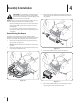
4 Assembly & Installation CAUTION: Do not attempt to install this bagging attachment on the tractor while it is still hot from operation. Do not attempt to install this bagger until the tractor has fully cooled down. 3. Remove the two (2) muffler shield mounting brackets as shown in Figure 4-2. Retain these brackets and screws for reinstallation. 4. Remove the muffler shield as shown in Figure 4-3. 5.
Figure 4-4 6. Install long muffler deflector onto the muffler of the tractor by installing the four (4) 710-0227 tap screws included in hardware pack 689-00343. See Figure 4-5. Figure 4-6 8. Install the muffler shield, removed in step 3, into the muffler shield mounting bracket as shown in Figure 4-7. Secure with the four tap screws removed in step 2. NOTE: Position the muffler deflector with the exhaust tube pointed toward the outside (right side) of the tractor, as shown in the inset of Figure 4-5.
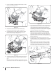
9. Position the muffler and bumper shield into place on the tractor, as shown in Figure 4-8. Figure 4-10 13. Figure 4-8 10. Re-install the rear hitch plate removed earlier using hardware from the pack 689-00343. See Figure 4-9. 11. Install the bumper over the muffler and bumper shield held in place, and secure with the two remaining tap screws removed in step 1. See Figure 4-9.
15. Install the bagger cross-support bracket with the flange facing outward, as shown in Figure 4-12, by attaching it to the side support brackets using four 710-04048 hex screws and 7123004A flange lock nuts from hardware pack 689-00338. 16. Further secure the bagger cross-support bracket to the tractor by installing four 710-04043 hex screws through the cross-support bracket and into the rear of the tractor frame. Secure using four 712-3004A flange lock nuts from hardware pack 689-00338.
22. If not already assembled by the factory, install the bagger screen into the bagger cover by first inserting the end closest to the center into the cutout mounting hole, as in Figure 4-16. Make sure to feed the screen under the lip, as in Figure 4-17. 24. Install the bagger cover onto the bag support assembly, as seen in Figure 4-18. The plastic cover goes inside of the two mounting tabs. Cover mounts in between these two tabs Figure 4-18 Figure 4-16 23.
27. Install the bag assemblies onto the bag support brackets by inserting the front edge in first, as seen in Figure 4-22, and setting the back edge down until it fits into the assembly. 1 2 Figure 4-20 26. Open the bagger cover by pushing in on the rear, right-side tab with your right hand, as seen in 1 of Figure 4-21, and lifting the cover with your left hand in the center rear of the bagger cover, 2.
Note: There are three different baffles included with this bagging kit, each is for a different sized deck. Using the parts list later in this manual, identify the proper deck baffle for the deck this bagger is being installed on. Also use the part list for the proper orientation of the deck baffle. Basically, the 48” and 60” deck baffles mount with the widest end towards the discharge chute, and the 54” deck baffle mounts with the narrow end towards the discharge chute. 4. 4.
6. Locate the upper chute tube and install the 723-04009A chute strap included in hardware pack 689-00340, to the upper chute tube using a 710-0924 machine screw and 712-04064 flange nut provided In hardware pack 68900337. See Figure 4-26. 4. Insert the end of the discharge chute top mounting bracket into the hole provided on the cutting deck as detailed in 2 of Figure 4-28. 5.
7. Install the chute adapter onto the chute elbow by lining up the tabs and sliding the adapter over the chute elbow, as shown in Figure 4-30. Secure the chute adapter by installing two 710-3013 hex screws into the holes shown and secure with two 712-0442 cap lock nuts, included in hardware pack 689-00337. 9. Secure the upper chute tube to the lower discharge chute by stretching the rubber strap on the upper chute tube downward and hooking it onto the pin on the lower chute tube. See Figure 4-32. 10.
5 Operation Bagger Usage 3. NOTE: When all of the grass bags are full, place the tractor on a firm, level surface, disengage the PTO, turn the tractor engine off and set the parking brake. 1. Pivot the seat forward and up. 2. Lift up grass bag cover by pushing in on the rear, right-side tab with your right hand, as seen in 1 of Figure 5-1, and lifting the cover with your left hand in the center rear of the bagger cover, 2. Do not remove the chute tube assembly from the tractor.
19A70046100 Parts List 3 2 1 6 4 18 5 7
Rear Bumper & Muffler Deflector Ref. Part Number Description 1. 703-09302A Rear Bumper 2. 703-09615 Bumper Mount Muffler Sheild 3. 710-0227 #8 AB Screw, 18 x .500 4. 710-04043 Hex Flange Screw, 5/16-18 5. 710-04484 Tap Screw, 5/16-18 x .750 6. 712-3004A Flange Lock Nut, 5/16-18 7.
19A70046100 Parts List 26 14 41 3 6 5 43 10 30 29 42 12 4 1 19 15 36 1 31 4 2 1 13 34 37 35 8 38 33 27 32 16 33 28 35 18 17 20 39 25 21 7 40 9 11 40 24 20 23 22 1
Bagger Components Ref. Part Number Description 1. 912-3027 Hex Flange Nut, 1/4-20 2. 736-0270 Bevel Washer, .265 x .750 x .060 3. 912-0442 Cap Lock Nut, 1/4-20 4. 710-0751 Hex Head Screw, 1/4-20 x .620 5. 710-3013 Hex Head Screw, 1/4-20 x .50 6. 736-3092 Flat Washer, .265 x 1.0 x .030 7. 712-04064 Flange Lock Nut, 1/4-20 8. 603-05167 Bagger Bracket Assembly 9. 723-04009A Chute Strap, 11.65" Lg. 10. 911-04069 Grass Catcher Pin, 1/4-20 11. 710-0924 Machine Screw, 1/4-20 x 0.
Notes 22
CUB CADET LLC MANUFACTURER’S LIMITED WARRANTY FOR SEPARATELY SOLD ATTACHMENTS AND ACCESSORIES IMPORTANT: To obtain warranty coverage owner may be required to present an original proof of purchase and applicable maintenance records to the servicing dealer. Please see the operator’s manual for information on required maintenance and service intervals.