
Operator's Manual

ASSEMBLY & INSTALLATION
6
NOTE: References to left, right, front and rear of the tractor are from the operator’s position, unless
otherwise stated.
• Before assembly, place the tractor on a firm, level surface, disengage the
PTO, stop the tractor engine and set the parking brake.
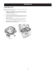
Assemble Mounting Brackets
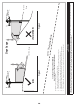
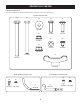
1. Install 12 rubber pads (735-05938) into
adapter bracket (789-02518) using the
mounting holes shown in Figure 3.
NOTE:
Check the bumper pads after each season
for excessive wear and replace as necessary.
Install Bracket
Assembly on Tractor
NOTE: When assembling this mounting assembly, it is best to not fully tighten the bracket at this time.
This will facilitate the mounting process in later steps, which will then require fully tightening this
mounting assembly.
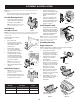
Install mounting bracket assembly on
tractor as follows:
1. Remove hitch bracket.
2. Place two flat washers (736-0117)
between hitch bracket adapter (789-
02298) and the hitch bracket
removed in Step 1.
3. Install bracket assembly to the
tractor’s lower frame with two
capscrews (710-0376). See Figure 4.
4. Hang adapter bracket assembly
onto upper frame tube and connect
to hitch bracket adapter with two
screws (710-0376), two cup washers
(736-0242) and two flange lock nuts
(712-04063). See Figure 5.
NOTE: Make sure the adapter bracket is
seated firmly on the upper tube frame.
5. Tighten all of the hardware installed
at this time.
Install Vertical Support
NOTE: This manual covers various bagger
configurations. Please follow the instructions
applicable to your machine.
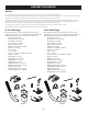
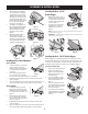
1. Using Figure 6 and the chart below, locate
the correct mounting hole location on the
mounting bracket for your tractor:
Model No. Description Position
19B70054* 42”/46” Double Bagger 4
19B70055* 50”/54” Double Bagger 3
NOTE: Hole position 2 is currently not used.
2. Install the vertical support (683-
04519C) onto the mounting assembly
on the tractor by hooking it over the
mounting assembly as shown in
Figure 7.
3. Secure the vertical support to the
mounting assembly using a hex
bolt (710-0376) and flange lock nut
(712-04063) from hardware pack
689-01419. See Figure 7.
Install Hanger Assembly
1. Install and secure the hanger assembly
(683-04461C) onto the vertical support
using two carriage bolts (710-0276), two
cup washers (736-0242) and two flange
lock nuts (712-04063) from hardware
pack 689-01419. See Figure 8.
NOTE: The carriage bolts (710-0276), from hardware
pack 689-01419, go in the top hole with the nut facing
the engine. The hex bolt (710-0376), from the same
hardware pack, goes in the bottom hole.
Assembling Remaining
Bagger Components
With the mounting brackets assembled and in place on the tractor, follow these
steps to assemble the remaining bagger components.
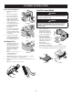
1. Snap the upper chute support
(731-17091) in place by first clipping
the side portion onto the hanger
assembly rail (1), as shown in Figure 9.
2. Snap the front side of the upper
chute support to the rail (2), as
shown in Figure 9.
3. If not already done so by the factory,
install the screen (731-06504) into
the bagger cover (631-04292) by first
inserting the end closest to the side
with the cut-out (1) into the
mounting hole, as in Figure 10.
4. Make sure to feed the screen under
the lip. Clip in the other side by
pushing the screen into the provided
cut-out (2). See Figure 11.
5. Install the bagger cover onto the
hanger assembly, as seen in Figure 12.
The cover goes inside the two
mounting tabs.
Figure 3
Figure 4
Figure 5
Figure 6
Figure 7
Figure 8
Figure 9
1
Figure 10
Make sure screen sits
under the cover’s lip
2
Figure 11
Figure 12
Figure 13
Figure 14