
Operator's Manual
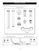

ASSEMBLY & INSTALLATION
7
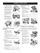
6. Slide the hinge pin (711-04988) into
the hole located on the mounting tab,
as shown in Figure 13. Use the cut-out
window (see inset in Figure 13) to line
up the hinge pin on the other side and
push pin all the way in until it reaches
the end-stop. At this point the pin clips
into place and is secured by a tab in
the bagger cover. See Figure 14.
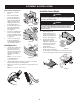
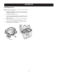
7. Open bagger cover by pushing in on
the rear, right-side tab with your right
hand (1), and lifting the cover with
your left hand in the center rear of
the bagger cover (2) as shown in
Figure 15.
8. Install both grass bag assemblies
(664-05104) onto the hanger
assembly rails by inserting the front
edge in first (1), and then setting the
back edge down until it fits into the
assembly (2), as shown in Figure 16.
Installing the Boot Rod & Hardware
Model 19B70054*:
1. From the inside of the boot, put the two
hex head screws (738-1225), from
hardware pack 689-00636, through the
holes at the bottom front of the boot.
See Figure 17.
2. Put the mounting rod (747-06043) in
place over the hex head screws. Make
sure the tip of the rod is facing out from the boot. See Figure 17.
3. Begin threading the two flange lock nuts (712-04064) onto the hex head
screws. See Figure 17.
4. Using a 7/16-inch wrench or socket on the screw and a 7/16-inch box wrench
on the lock nuts, tighten down so flange is flush to secure the assembly.
Model 19B70055*:
1. From the inside of the boot, put the
two hex head screws (738-1225), from
hardware pack 689-02199, through the
holes at the bottom front of the boot. See
Figure 18.
2. Put the mounting rod (747-06309) in
place over the hex head screws. Make
sure the tip of the rod is facing out from
the boot. See Figure 18.
3. Begin threading the two flange lock nuts (712-04064) onto the hex head
screws. See Figure 18.
4. Using a 7/16-inch wrench or socket on the screw and a 7/16-inch box wrench
on the lock nuts, tighten down so flange is flush to secure the assembly.
Installing the Boot - 42”/46”
Double Bagger
1. With the tractor’s discharge chute
raised up and held open (1), install the
boot by placing the boot mounting
rod into the chute mounting tab (2),
as shown in Figure 19.
2. Secure the boot to the deck using
a wing knob (720-04122) from
hardware pack 689-01419. See
Figure 20.
NOTE: If present, remove the protective cap off of the mounting stud on the mowing deck as
shown in the upper inset of Figure 20.
IMPORTANT! Be certain that the bottom of the discharge chute is located inside of the lip of
the deck opening, as shown in Figure 21.
Installing the Boot - 50”/54” Double Bagger
When installing the boot, two different installation instructions exist. For the 54-
inch fabricated deck units, the boot mounts directly onto the cutting deck. For the
50-inch and 54-inch stamped decks, an adapter must first be installed. Be sure to
follow the instructions that pertain to the unit you are installing this bagger on.
54” Fabricated Deck Units:
1. Raise the deck to its highest position.
2. Raise the chute deflector (1 in
Figure 22) on the deck and hold it
while you position the boot over
the chute opening.
3. Insert the end of the boot (2) into
the hole provided in the deck wheel
mount as shown in the inset of
Figure 22.
4. Pivot the boot until the hole in the
boot aligns with the pin on the deck.
Move the boot down onto that pin as
shown in (3) of Figure 22.
5. Secure the boot to the cutting deck
using a wing knob (720-04122) from
hardware pack 689-01419. Refer to
Figure 23.
Figure 15
2
1
Figure 16
Figure 17
Figure 18
1
2
Figure 19
1
2
Figure 20
Figure 21
1
2
3
Figure 22
Figure 23
2. Install the vertical support (683-
04519C) onto the mounting assembly
on the tractor by hooking it over the
mounting assembly as shown in
Figure 7.
3. Secure the vertical support to the
mounting assembly using a hex
bolt (710-0376) and flange lock nut
(712-04063) from hardware pack
689-01419. See Figure 7.
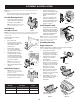
Install Hanger Assembly
1. Install and secure the hanger assembly
(683-04461C) onto the vertical support
using two carriage bolts (710-0276), two
cup washers (736-0242) and two flange
lock nuts (712-04063) from hardware
pack 689-01419. See Figure 8.
NOTE: The carriage bolts (710-0276), from hardware
pack 689-01419, go in the top hole with the nut facing
the engine. The hex bolt (710-0376), from the same
hardware pack, goes in the bottom hole.
Assembling Remaining
Bagger Components
With the mounting brackets assembled and in place on the tractor, follow these
steps to assemble the remaining bagger components.
1. Snap the upper chute support
(731-17091) in place by first clipping
the side portion onto the hanger
assembly rail (1), as shown in Figure 9.
2. Snap the front side of the upper
chute support to the rail (2), as
shown in Figure 9.
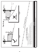
3. If not already done so by the factory,
install the screen (731-06504) into
the bagger cover (631-04292) by first
inserting the end closest to the side
with the cut-out (1) into the
mounting hole, as in Figure 10.
4. Make sure to feed the screen under
the lip. Clip in the other side by
pushing the screen into the provided
cut-out (2). See Figure 11.
5. Install the bagger cover onto the
hanger assembly, as seen in Figure 12.
The cover goes inside the two
mounting tabs.
Figure 8
Figure 9
1
Figure 10
Make sure screen sits
under the cover’s lip
2
Figure 11
Figure 12
Figure 13
Figure 14