
Operator's Manual

ASSEMBLY & INSTALLATION
8
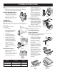
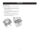
On 50” and 54” Stamped Decks:
1. Raise the deck to its highest
position.
2. Remove the deck pin rubber
protective cap (1) in Figure 24.
3. Raise the chute deflector (2 in
Figure 24) on the deck and hold
it while you install the chute
adapter (731-10133) (3) onto the
deck as shown in Figure 24.
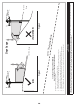
4. Insert the end of the boot (1) into
the hole provided in the deck
wheel mount as shown in the
inset of Figure 25.
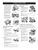
5. Pivot the boot rearward until the
hole in the boot aligns with the
pin on the deck adapter. Move the
boot down onto that pin as shown
in 2 of Figure 25.
6. Secure the boot to the cutting
deck using a wing knob (720-
04122) included in hardware pack
689-01419. Refer to Figure 26.
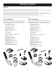
Installing the Hose
1. Thread the upper end of the hose
(764-05082) securely into the
upper chute support. There are
two tabs on the lower inside part
of the upper chute support to
allow for secure threading. See
Figure 27.
NOTE: The hose and upper chute support
are left-hand threaded. Thread
counter-clockwise until secure.
2. Lift by the handles at the bottom of the hose. Slide the hose over the boot
mounted on the cutting deck, as shown in Figure 28.
3. Make sure the connection is secure and there are no gaps between the hose
and the boot.
NOTE: If open, close the bagger cover prior to mowing.
Install the Counter Weight
WARNING
This front-weight kit is required when operating any compatible zero-turn
tractor models equipped with a grass collector. Failure to install this kit
may result in serious injury or death.
WARNING
Before beginning installation, place the zero-turn tractor on a firm and
level surface, set the parking brake, place the PTO in the disengaged
(OFF) position, stop the motor and remove the ignition key to prevent
unintended starting.
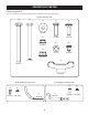
1. Before assembly, peel the
adhesive decals from the sheet
and apply to the inside faces of
the right and left weight hanger
brackets, as shown in Figure 29.
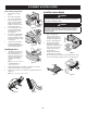
2. Attach the weight and three
weight plates to the weight
hanger brackets with two 3/8-inch
hex head capscrews (710-3085)
and two nuts (712-04065) as
shown in Figure 30.
3. Visually center the weight bar
assembly on the tractor and using
two 7/16-inch hex head capscrews (710-3056) and two nuts (712-04063)
secure the counter weight assembly to the tractor as shown in Figure 31.
1
3
2
Figure 24
1
2
Figure 25
Figure 26
Figure 27
Figure 28
Figure 29
Figure 30
Figure 31