Hydrostatic Zero-Turn Commercial Riding Mower ProfessionalTurf Equipment MODEL 19HP Enforcer 44 21HP Enforcer 48 23HP Enforcer 54 OPERATOR’S AND SERVICE MANUAL
TABLE OF CONTENTS Foreword. . . . . . . . . . . . . . . . . . . . . . . . . . . . . . . . . . . . . . . . . . . . . . . . . . . . . . . . . . . . . . . 3 General Safety Operations . . . . . . . . . . . . . . . . . . . . . . . . . . . . . . . . . . . . . . . . . . . . . . . . . 4 A. General Operation . . . . . . . . . . . . . . . . . . . . . . . . . . . . . . . . . . . . . . . . . . . . . . . . . 4 B. Slope Operation . . . . . . . . . . . . . . . . . . . . . . . . . . . . . . . . . . . . . . . . . . . . . .
FOREWORD The Hydrostatic Zero-Turn Riding Mower provides superb maneuverability and mid-mount cutting. The machine incorporates many safety features that should be studied by all operators before use. The list of safety precautions should receive particular attention. This manual presents all of the operating and maintenance instructions necessary to keep your mower at peak efficiency. If operated and maintained properly, your mower will give dependable service.
WARNING • • • The engine exhaust, some of its constituents, and certain vehicle components contain or emit chemicals known to the State of California to cause cancer, birth defects or other reproductive harm. This unit is equipped with an internal combustion engine and should not be used on or near any unimproved forest-covered, brush-covered, or grass-covered land unless the engine’s exhaust system is equipped with a spark arrester meeting applicable local or state laws (if any).
17. 18. 19. 20. 21. 22. • Use slow speed. Choose a low enough speed so that you will not have to stop while on the slope. • Follow the manufacture’s recommendations for counterweights with attachments to improve stability. • Use extra care with grass catchers (material collection systems) or other attachments. These can change the stability of the machine. • Keep all movement on the slopes slow and gradual. Do not make sudden changes in speed or direction.
7. Remove the key when the machine is left unattended to prevent unauthorized operation. D. SERVICE 1. 2. 3. 4. 5. 6. 7. 8. 9. Use extreme care in handling gasoline and other fuels. They are extremely flammable and the vapors are explosive. a. Use only an approved container. b. Never remove fuel cap or add fuel with the engine running. Allow the engine to cool at least two minutes before refueling. c.
and is contained within the positive and negative terminals as well as within the battery’s internal gridwork of plates and active materials. 2. A. Explosive gases are generated when batteries are re-charged, so sparks, flames and heat sources should be avoided. Loose connections at the battery terminals can produce sprks and heat...connections to the terminals must be kept tight, and the terminals and battery surfaces kept clean of acids and corrosion.
SAFETY DECALS AND LABELS DANGER KEEP HANDS AND FEET AWAY. DO NOT OPERATE MOWER UNLESS CHUTE DEFLECTOR OR ENTIRE GRASS CATCHER IS IN ITS PROPER PLACE. S30503 ASSEMBLE CHUTE DEFLECTOR TO THIS UNIT BEFORE OPERATING. Part Number: 777I22444 Part Number: 777S30503 TO REDUCE THE RISK OF INJURY, D O N OT O P E RAT E M OW E R U NL E S S DISCHARGE CHUTE COVERORGRASS C A T C H E R IS I N I T S P R O P E R P L A C E .
SPECIFICATIONS GENERAL INFO. Controls: Engine ignition and start switch; throttle & choke; left and right steering levers; electric blade clutch switch; parking brake; mower deck lift Parking Brake: Mechanical linkage attached to the brake handle Seat: Weight adjustable suspension seat with adjustable seat back and armrest. 4" Adjustment front-to-rear Frame: Structural steel, all welded construction Instrumentation: Hour meter Front Caster Wheels: 11 x 6.00 - 5 Drive Wheels: 20 x 8.
OPERATING INSTRUCTIONS Figure. 1 Figure. 2 parking brake Hour Meter Electric Blade Clutch Switch Ignition Switch Choke E. General Engine throttle maintain the uphill side lap bar “essentially” in a fixed position. k. Be careful when crossing gravel paths or roadways. Always turn off the blade clutch switch and wait until the blades stop rotating and raise the cutting deck to the transport position. Always allow other vehicles to have the right of way. l.
next and each subsequent time that the area is mowed. 2. Safety Awareness when Mowing a. Do not operate on steep slopes, those above 15 degrees (27% slope). b. Avoid turning downhill if possible, use extra care and go slowly. c. Avoid turning when going downhill, traction is at a minimum going downhill. d. Do not operate with discharge side of the mower toward streets, buildings, playgrounds, parking lots, other machines, animals, and other people. e.
Steering Levers Figure. 4 Figure. 3 Fuel Shutoff Valve 8. Seat Position Adjustment Lever: The Seat Position Adjustment Lever is located beneath the seat. The Seat Position Adjustment Lever is used to move the seat forward and backward. To place the seat in the desired position pull the seat adjustment lever to the left then push the seat forward or back to the desired position. Release the lever so the seat will lock in place. 9.
G. Initial Adjustments switch, remove connection of the spark plugs and using the foot pedal, lower the mowing deck into the cutting position. Using a ruler, pencil and paper, measure and note the distance from the paved surface to the bottom edge of the mowing blade at the front and the back of the deck on each side of the mower. (Four dimensions.) 1. Check the fluid levels and tires: Note: These checks should be made daily, before starting the engine. b. a.
5. Lubricate all fittings listed in the maintenance section. 1. Make sure the park brake is set to the “ON” position, both lap bars are in the neutral/start position, and the Power Take Off (PTO also referred to as blade control switch) is in the “off” (down) position. 2. Move the choke and the engine speed control (throttle) forward to the end of the slot. 3.
toward the opposite from the side that was advanced — I.E. to turn clockwise (to the Right), move the LEFT lap bar forward more than the right side, and to turn counter-clockwise (to the LEFT), move the RIGHT lap bar forward more than the left side. NOTE: If one lap bar is in the neutral position and the other is advanced, the turn side tire will not rotate and a “pivot turn” will be executed — turf defacement could occur (if on grass) as well as potential damages to the traction surface and the tire.
d. Turn the electric blade clutch switch “Off”. e. Push the choke/throttle control to the full forward position. f. Insert the key in the ignition and start switch and turn the switch to “On”. g. Turn the ignition key in a clockwise direction to the “Start” position until the engine starts. j. k. Note: Do not hold the key in the “Start” position for more than 10 seconds or you may damage the starter. If the engine does not start in this time, wait about 30 seconds and try again. 5. h.
Trailing Link hair pin hair pins Figure. 6 without offset, and with a maximum amount of sharpened cutting edge. c. Mulch- These blades are generally designed for use in cutting decks equipped with mulch baffles. The shape of the blade generally produces higher turbulence in order that the grass can be repeatedly cut and re-cut into smaller pieces. These blades generally require more horsepower than other blades.
m. Clean up the grass clippings and other materials washed from underneath the mower deck, and dispose of them properly. Hose Coupler (Shown without Hose Attached) g. To replace the blade reverse the above process and tighten nut to 100-120 lb ft. Note: Add a small amount of multi-purpose grease to the bolt threads to avoid corrosion and galvenic action WARNING: Never mow with dull blades! Blades that are bent should be replaced! The cutting blades are sharp and can cause severe injury.
D.Electrical Circuit Danger: Read General Safety Precautions Nos. 9 and 10. 1. Battery: The battery is located beneath the operator’s seat. If so equipped, remove the fillcaps and check the level of the liquid electrolyte in the battery every 50 operating hours. If the level in any of the six cells has dropped below the bottom of the split ring inside the fill hole, refill the cell with distilled water.
seat switch must be replaced or the electric PTO clutch must be repaired. The airgap should be checked every 100 hrs. (or less, if severe operating conditions exist such as when there are many on/off cycles, mulching operations, material collection systems used, and dusty/dirty conditions), and the air-gap adjusted if more than 0.025". To inspect, remove the “negative” cable from the battery and all sparkplug wires. The air-gap should be checked with feeler gages in the three slots of the BBC (PTO Clutch).
the axle assembly and pull the axle assembly from the caster yoke. The wheel and two spacer sleeves will drop free. Slip the axle assembly through one side of the caster yoke, through a spacer sleeve, a wheel, the other spacer sleeve and finally through the other side of the caster yoke. Then tighten the locknut on the end of the axle assembly. stop when you dismount from the operator’s seat, the seat switch must be replaced. d.
spray paint. Brush a rust preventive oil on any unpainted surfaces including the pulleys and blades. (Be careful not to get any oil on the drive belts.) d. Lubricate the mower. e. Drain the engine oil. The engine should be warm so that all the oil drains. Replace the engine oil filter and refill the crankcase with fresh oil. f. Gasoline Engine: Drain all the fuel. Close the fuel tank shutoff valve. Disconnect the fuel line from the carburetor and put the end into an approved fuel container.
MAINTENANCE SCHEDULE 6. D. Every 100 Hour Checks A. Daily Checks 1. 1. Before starting engine: a. Check the fuel level by viewing in the tank. b. Check the engine oil level.** c. Check the hydraulic transaxels for leaks. d. Check the tires and tire pressure. Drive Tires: 8-10 psi. Front Caster Wheels: 20-25 psi. e. Check the spindle belt, the mower drive belt and the hydro drive belt. f. Check the blades. Make sure they are sharp and that the blade securing cap screws are tight. g.
. OIL CHART Apply a few drops of SAE 15W-40 engine oil, grease, or use a spray lubricant. Apply the oil to both sides of pivot points. Wipe off any excess. Start engine and operate mower briefly to insure that oil spreads evenly.
Performance Adjustments B. Engine RPM Check and Adjustment Table 1 A. High Speed Tracking Adjustment If mower tracks to one side with both lap bars in fully forward position: 1. Check air pressure in all four tires: a. Pressure should be within specified ranges and balanced side-to-side. b. Rear tires 8-10 psi recommended (20 psi MAX.) c. Front tires 20-25 psi recommended (28 psi MAX. 2.
C. Deck Corner Ball Wheel Roller Settings c. Replace the bolts and nuts, and tighten to 28-34 ft-lbs. 1. If angular adjustments are also required, nuts can be tightened until snug at this point. d. The same adjustments should be made to both sides of the mower. 5. To adjust the front-to-rear angle of the lap bars, a. Loosen the nuts on the lap bar mounting bolts, leaving the bottom one fairly snug. b. The top hole is slotted, allowing the lap bar to pivot on the bottom bolt. c.
F.Deck leveling Procedure Outer Jam Nuts 1. Park the mower on a flat paved surface, engage the parking brake, shut off the engine, remove the key from the ignition switch, disconnect the spark plug wires and using the lift pedal, position the mowing deck into the 3" height of cut position. (The 3" height of cut position is recommended in order for one to see and obtain a measurement. Any height of cut position is acceptable as long as a proper measurement can be taken.) 2.
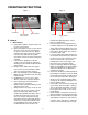
WIRING DIAGRAM GD: 02003651 28
SLOPE GAUGE TTE A1 5 ° S LOP E OR A FENCE POST A CORNER OF A BUILDING A POWER POLE SIGHT AND HOLD THIS LEVEL WITH A VERTICAL TREE USE THIS PAGE AS A GUIDE TO DETERMINE SLOPES WHERE YOU MAY NOT OPERATE SAFELY. FO L D O N DO D LI N E , REP RE S E NTIN G 15° WARNING Do not mow on inclines with a slope in excess of 15 degrees (a rise of approximately 2-1/2 feet every 10 feet). A riding mower could overturn and cause serious injury.
MAINTENANCE RECORD DATE WORK PERFORMED DATE 30 WORK PERFORMED
MANUFACTURER’S LIMITED WARRANTY FOR CUB CADET COMMERCIAL ENFORCER ZERO-TURN COMMERCIAL RIDING MOWER IMPORTANT: To obtain warranty coverage owner may be required present proof of purchase and applicable maintenance records to the servicing dealer. Please see the operator’s manual for information on required maintenance and service intervals. In addition, Cub Cadet may deny warranty coverage if the hour meter, or any part thereof, is altered, modified, disconnected or otherwise tampered with.