Safe Operation Practices • Set-Up • Operation • Maintenance • Service • Troubleshooting • Warranty Operator’s Manual 4 x 4 Utility Vehicle — Models 37BM46ED710, 37BM466D710, 37BM467D710, 37BM46GD710 & 37BM465D710 WARNING READ AND FOLLOW ALL SAFETY RULES AND INSTRUCTIONS IN THIS MANUAL BEFORE ATTEMPTING TO OPERATE THIS MACHINE. FAILURE TO COMPLY WITH THESE INSTRUCTIONS MAY RESULT IN PERSONAL INJURY. CUB CADET LLC, P.O. BOX 361131 CLEVELAND, OHIO 44136-0019 Printed In USA Form No.
1 To The Owner Thank You Thank you for purchasing a Utility Vehicle manufactured by Cub Cadet LLC. It was carefully engineered to provide excellent performance when properly operated and maintained. Please read this entire manual prior to operating the equipment. It instructs you how to safely and easily set up, operate and maintain your machine. Please be sure that you, and any other persons who will operate the machine, carefully follow the recommended safety practices at all times.
Important Safe Operation Practices 2 WARNING: This symbol points out important safety instructions which, if not followed, could endanger the personal safety and/or property of yourself and others. Read and follow all instructions in this manual before attempting to operate this machine. Failure to comply with these instructions may result in personal injury. When you see this symbol.
15. Inspect area around vehicle before moving, especially in reverse. Back up slowly. Always look down and behind before and while backing to avoid a back-over accident. Keep bystanders out of area. 32. Always inspect your vehicle each time you use it to make sure it is in safe operating condition. Always follow the inspection and maintenance procedures and schedules described in this manual. 16. Avoid driving through water, since loss of control may occur.
Cargo Box Loading/Operation Children 1. Do not exceed vehicle’s Total Load Capacity rating of 1,400 lbs. This includes operator, passenger, accessories, and cargo. 1. 2. Do not exceed 1000 lbs. load in cargo box. 3. Spread load evenly and secure to prevent movement. 4. Do not load above height of cargo box front panel. Load could shift forward and injure driver or passenger. 5. Tragic accidents can occur if the operator is not alert to the presence of children.
f. Never fuel machine indoors. 11. g. Never remove fuel cap or add fuel while the engine is hot or running. Allow engine to cool at least two minutes before refueling. Observe proper disposal laws and regulations for gas, oil, etc. to protect the environment. 12. h. Never over fill fuel tank. Fill tank to no more than ½ inch below bottom of filler neck to allow space for fuel expansion.
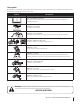
Safety Symbols This page depicts and describes safety symbols that may appear on this product. Read, understand, and follow all instructions on the machine before attempting to assemble and operate. Symbol Description READ THE OPERATOR’S MANUAL(S) Read, understand, and follow all instructions in the manual(s) before attempting to assemble and operate WARNING— HOT SURFACE Hot Surface - Do not touch. WARNING — FUEL CONTAINER Avoid injury from explosion.
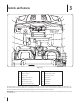
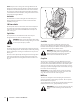
3 Controls and Features F A G B H I C J D K E L M N Figure 4-1 A Check Engine Light H 4x4 Switch B Ignition Switch I 12 Volt Power Outlet C Brake Pedal J Accelerator Pedal D Differential Lock Lever K Shift Lever E Parking Brake Lever L Cup Holders F Warning Light Cluster M Seat Belts G Engine Over-Temp Light N Fuel Tank Read this operator’s manual, safety labels, and operating instructions on the vehicle before operating.
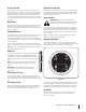
Accelerator Pedal Engine Over-Temp Light The accelerator pedal is located on the right side of the floor beneath the dash panel. Depressing the accelerator pedal will move the vehicle in the direction selected on the gearshift. As the pedal is depressed, speed will increase to the maximum selected range. Releasing the pedal reduces the speed, but does not stop the vehicle. The brake must be applied to stop vehicle. See Fig. 4-1.
NOTE: Every 50 hours a “change oil” message will flash on the display for 2 minutes every time the UV is started. This message will repeat for the first two minutes after each 50 hour interval. The oil pressure indicator light will also flash when this display is active. Before the interval expires, change the crankcase oil as instructed in the Engine Manual. 4x4 Switch The 4x4 switch is located on the right side of the dash panel. Push in top/bottom of switch to activate or deactivate 4x4 capability.
4 Operation Filling Fuel Tank Stopping Engine 1. Stop vehicle on a level surface and apply parking brake. 1. 2. Turn the ignition key to the STOP position and remove the key. To stop utility vehicle, release accelerator pedal and depress brake pedal until vehicle comes to a complete stop. 3. Allow engine to cool several minutes before you add fuel. 2. Move shifter back into Neutral. 4. Clean area around fuel cap and remove cap. 3. Lock parking brake and turn key switch to STOP position. 5.
7. Release accelerator and apply brake pedal evenly and firmly to slow down or stop. Engaging 4x4 Electric Lift (Optional) 1. Park the vehicle safely and turn key to the RUN position. 2. Raise cargo box by pressing and holding top of electric lift switch. Release switch when box is at desired dump height or when maximum height is reached. The 4x4 switch is located on the right side of the dash panel. See the Controls & Features section. 1.
Towing Loads WARNING: To help prevent personal injury due to loss of control or tipping, always tow a load slow enough to maintain control. 1. Do not tow a load that exceeds 1,400 lbs. rolling weight (i.e. trailer plus cargo) and never exceed 140 lbs. tongue weight. 2. Go slow when towing a heavy load. Allow for increased braking distance. Tow load at a speed slow enough to maintain control. 3. Do not tow on slopes greater than 5°. 4.
5 Maintenance & Adjustments Engine Use a permanent type antifreeze containing corrosion and rust inhibitors. Dilute the antifreeze with water at a 1 : 1 ratio to mix the coolant solution (50% antifreeze : 50% water). Air Filter The engine air filter should be changed every 50 hours. Change more frequently if operated in extremely dusty conditions. 1. Pull up on latch and turn counter-clockwise to release air cleaner cover. See Fig. 6-1.
If the overflow reservoir is empty, the radiator cap should be removed and the coolant level in the radiator checked before adding coolant to the reservoir. If necessary, first refill the system through the radiator filler neck as follows: WARNING: It is dangerous to remove the radiator cap when the system is hot. Allow the system to cool before removing the radiator cap. 1. Turn the radiator cap counterclockwise to the first stop to release any pressure. 2.
Battery Tire Pressure WARNING: The battery produces a flammable and explosive gas. Do not smoke near battery. Wear eye protection and gloves when handling the battery. Do not allow direct metal contact across battery posts. The battery is sealed and is maintenance free. Acid levels cannot be checked and fluid can not be added.
Ball Joints Draining CVT Cover Inspect the upper and lower front A-arm ball joints on each side of the vehicle and the two tie rod ends for wear every 100 hours or once a year. See Fig. 6-5. If excessive wear appears, have ball joints or tie rod ends replaced by your local Cub Cadet dealer. Drain CVT cover every 50 hours or after driving vehicle through more than 12” of water. 1. Remove CVT cover drain plug. See Fig. 6-7.
6 Service Headlight Bulbs Fuses 1. Raise hood to get access to the headlight assembly. 1. 2. Turn the bulb/socket assembly approximately a quarter turn counterclockwise to align its tabs with the notches of the reflector, then remove from the reflector. See Fig. 7-1. Unlatch and lift hood forward to get access to under the dash panel. 2. Remove fuse holder cover. See Fig. 7-2. Figure 7-2 Figure 7-1 18 3. Unplug the wire harness from the bulb/socket assembly. 4.
Wheels Changing Brake Pads WARNING: Using an unstable lifting device and vehicle support may result in bodily injury. Use a safe lifting device and supports to work on raised vehicle. 1. Stop the vehicle on a level surface and apply parking brake. 2. Turn the ignition key to the STOP position and remove the key. 3. Loosen but do not remove the five lug nuts from the axle hub. See Fig. 7-3. WARNING: Using an unstable lifting device and vehicle support may result in bodily injury.
7 Maintenance Chart Maintenance Schedule Before Each Use First 10 Hours Every 20 Hours/2 mo. Every 50 Hours P Check Transfer Case Oil P Change Transfer Case Oil* P Tighten Wheel Bolts P Change Air Filter^ Check Engine Coolant Level Every 100 Every 500 Hrs. or Yearly Hrs. or 2 Yrs.
8 Accessories NOTE: For parts or accessories, contact your local Cub Cadet dealer. To locate the dealer nearest you call 877-282-8684 or log onto www.cubcadet.com.
9 Specifications NOTE: Specifications subject to change without notice. Engine/Electrical Dimensions Make 31HP* Kohler® Aegis EFI Length/ Width 119” x 63.5” Type/ Cylinders 4 Cycle Gas/ 2 Cylinders Tread Center F: 52”/ R: 50” Displacement 748cc Height (Overall) 78” Maximum Torque 47.7ft. Lb. at 2400rpm Wheelbase 78” Ignition Mechanically Controlled 1,650 lbs.
10 Troubleshooting Problem Engine will not start Cause(s) 1. Battery has low voltage. 2. Loose or corroded battery connections. 3. Fuse is blown. 4. Spark plug wire is loose or disconnected. 5. Faulty spark plug or coil. 6. No Fuel or improper fuel. 7. Plugged fuel filter. 8. Defective starter solenoid. 9. Open-circuit in wiring. Engine is difficult to start 1. Engine is cold. 2. Plugged fuel filter. 3. Engine oil viscosity too heavy. 4. Spark plug is fouled. 5. Faulty spark plug or wire. 6.
Problem Engine overheats Cause(s) 1. Air cleaner element missing or plugged. 2. Engine oil low. 3. Engine operated too long at slow engine speed. Engine knocks 1. Low engine speed. 2. Stale or low octane fuel. 3. Engine overloaded. Engine loses power 1. Engine overheating. 2. Too much oil in engine. 3. Faulty spark plug. 4. Fuel supply being restricted. 5. Fuel filter plugged. 6. Fuel line pinched or kinked. 7. Fuel pump output not adjusted to specification. 8. Improper fuel. 9.
Problem Battery will not take a charge Cause(s) 1. Dead battery. 2. Loose or corroded connections. 3. Sulfated or worn-out battery. 4. Fluid level low. Difficult to shift Gears not lined up. Blip throttle and let it return to idle. If still hard to shift, contact your nearest Cub Cadet dealer.
FEDERAL and/or CALIFORNIA EMISSION CONTROL WARRANTY STATEMENT YOUR WARRANTY RIGHTS AND OBLIGATIONS MTD Consumer Group Inc, the United States Environmental Protection Agency (EPA), and, for those products certified for sale in the state of California, the California Air Resources Board (CARB) are pleased to explain the emission (evaporative and/or exhaust) control system (ECS) warranty on your outdoor 2006 and later small off-road spark-ignited engine and equipment (outdoor equipment engine) In California, n
WARRANTED PARTS: The repair or replacement of any warranted part otherwise eligible for warranty coverage may be excluded from such warranty coverage if MTD Consumer Group Inc demonstrates that the outdoor equipment engine has been abused, neglected, or improperly maintained, and that such abuse, neglect, or improper maintenance was the direct cause of the need for repair or replacement of the part.
CUB CADET LLC MANUFACTURER’S LIMITED WARRANTY FOR utility vehicles The limited warranty set forth below is given by Cub Cadet LLC with respect to new merchandise purchased and used in the United States, its possessions and territories, and by MTD Products Limited with respect to new merchandise purchased and used in Canada and/or its territories and possessions.