
Full Product Manual

7Section 2 — ASSembly & Set-Up
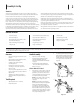
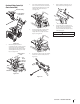
Refer to Figure 2-11 and proceed to your applicable Chute Control Style on pages 8-14.
Overhead Chute Control
(w/ Flex Shaft Steel Chute) Page 11
Electric Chute Control
Pages 12
Chute
Assembly
Chute
Assembly
Flex
Shaft
E-Z Chute™
Page 12
Chute Assembly
2-Way & 4-Way Chute Control
Page 10
Overhead Chute Control
(w/ Chute Control Rod) Page 9
Standard Side Crank Chute Control
Page 8
Standard Side Crank
Rod Assembly
Overhead Chute
Control Rod
Chute Control
Rod
Chute
Assembly
Chute
Assembly
Chute
Assembly
Chute Control
Rods
Figure 2-11
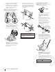
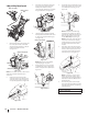
11. Insert a carriage screw (a) from the
outside through a handle tab (b), the
upper (c) and lower handles (d), a saddle
washer (e) and into the wing knob
(f). Repeat on the other side. Tighten
the wing knobs (f) on each side of the
handle. Refer to Figure 2-9.
(c)
(e)
(b)
(a)
(d)
(f)
Figure 2-9
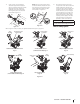
NOTE: The auger cable (a) routes down
the left lower handle and the drive cable
(b) is routed across the top of the lower
handle and down the right side of the
lower handle. See Figure 2-10.
(c)
(d)
(c)
(b)
(a)
(c)
(d)
Figure 2-10
12. Two cable ties (c) have been used to
loosely tie the control cables to the lower
handle, including the cable tie (c) you
relocated in step 3. A push clip (d) is also
included on the lower drive cable (b).
Position cable ties (c) now, as in Figure
2-10, and tighten to secure cables (a &
b) to the lower handle. Trim off excess
material of cable ties (c). If not already
installed, push the clip (d) on the drive
cable (b) into the hole in the handle
provided as shown in the left inset.
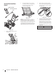
STOP
Refer to Figure 2-11 to identify your applicable chute
style and continue to Chute Assembly Options (page 7).
Chute Assembly Options