Operator’s Manual 4x2 Utility Vehicle Model 420A 430A 430D IMPORTANT: READ SAFETY RULES AND INSTRUCTIONS CAREFULLY Warning: This unit is equipped with an internal combustion engine and should not be used on or near any unimproved forestcovered, brush-covered or grass-covered land unless the engine’s exhaust system is equipped with a spark arrester meeting applicable local or state laws (if any). If a spark arrester is used, it should be maintained in effective working order by the operator.
TABLE OF CONTENTS Content Page Important Safe Operation Practices................................................................... 3 Know Your Utility Vehicle ................................................................................... 7 Operating Your Utility Vehicle ............................................................................ 10 Servicing Your Utility Vehicle ............................................................................. 13 Service Chart ..........................
SECTION 1: IMPORTANT SAFE OPERATION PRACTICES WARNING: This symbol points out important safety instructions which, if not followed, could endanger the personal safety and/or property of yourself and others. Read and follow all instructions in this manual before attempting to operate or service this vehicle. When you see this symbol - heed its warning.
Children 25. Do not start or operate vehicle in an inside area, unless it is adequately ventilated. Engine exhaust contains carbon monoxide fumes, which are very poisonous and can be deadly. 26. Do not change engine governor setting or over speed the engine. The governor is set at the factory for safe operating speed. 27. Assure safety interlock switch is adjusted correctly so engine cannot be started unless gearshift is in the neutral position. 28.
c. When practical, remove gas-powered equipment from the truck or trailer and refuel it on the ground. If this is not possible, then refuel such equipment on a trailer with a portable container, rather than from a gasoline dispenser nozzle. d. Keep the nozzle in contact with the rim of the fuel tank or container opening at all times until fueling is complete. Do not use a nozzle lock-open device. e. Extinguish all cigarettes, cigars, pipes and other sources of ignition. f. Never fuel machine indoors. g.
WARNING WARNING RIDERS CAN FALL OFF AND BE SERIOUSLY INJURED OR KILLED • This is an off-road utility vehicle. Do not operate on public highways. It handles and maneuvers differently than a normal passenger car. Sharp, high speed turns or abrupt maneuvers can cause vehicle to roll over or go out of control. • Handling and maneuvering characteristics of vehicle change depending upon cargo load. Heavy loads will affect steering, braking, stability and overall handling of vehicle.
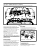
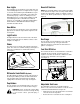
SECTION 2: KNOW YOUR UTILITY VEHICLE NOTE: Reference to right or left hand side of the utility vehicle is observed from the operating position. Figure 1 Brake Pedal Read this operator’s manual, safety labels, and operating instructions on the vehicle before operating. Compare the illustrations in this manual with your unit to familiarize yourself with the location of various controls and adjustments. Reference to the right or left hand side of unit is observed from the operating position.
• • 12V Power Outlet To engage the parking brake, push brake pedal down firmly, pull out on the parking brake latch, and release foot from brake pedal. Brake pedal will stay down and parking brake light on dash will come on to indicate parking brake is engaged. To release parking brake, push down on brake pedal and parking brake latch will release. The 12V power outlet is located on the right side of the dash panel.
Gear Lights Gearshift Switches The gear lights are located in the center and at the top of the warning light cluster. See Figure 6. Once a gear is selected, the instrument panel will illuminate a gear light or a combination of gear lights. If the vehicle has not shifted properly, or there is a shifting issue, the lights will flash for 5 seconds and an audible tone will sound. During this time a shift will not be allowed, however, once the lights stop flashing, shifting will be allowed.
lift, the cargo box can be raised to dump cargo. See Figure 11. WARNING: Make sure seat is in locked position prior to operation and do not try to adjust the seat position while operating the vehicle. WARNING: Do not exceed the vehicle’s Total Load Capacity of 1,200 lb., which includes driver, passenger, accessories, and cargo. Do not exceed 800 lb. in the cargo box. Cargo Box Seat Lever Figure 10 Cargo Box The cargo box is raised by a gas spring.
• • • • Disengaging Differential Lock (Optional) Release key to the RUN position when engine starts. If engine does not start, wait a few seconds and repeat procedures. After engine starts, push in choke knob. Release parking brake. • To disengage the differential lock, simply push the button again. The light will go off. Torque must be equal on both axles for differential lock to release. It is best to slow down and drive straight ahead at a constant speed when disengaging the differential.
Dumping Load From Cargo Box • • • Towing Loads Back up the vehicle to the dump site and apply parking brake. Unhook the tailgate from cargo box. If using an electric lift, raise cargo box to dump load and lower box when empty. WARNING: To help prevent personal injury due to loss of control or tipping, always tow a load slowly enough to maintain control. • WARNING: The center of gravity changes as a loaded cargo box is raised. Do not allow rear wheel to hang over the edge of a loading dock or ravine.
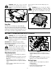
SECTION 4: SERVICING YOUR UTILITY VEHICLE Lubrication could change the polarity and cause damage to your engine’s alternating system. Front Axle Lubrication • Clean Battery and Terminals Lubricate one grease fitting on each axle with 2 or 3 shots of grease every 50 hours. • Engine • Read the Honda Engine operator’s manual for any service or maintenance information pertaining to the engine. • • Filling Fuel Tank • • • • • • • Stop the vehicle on a level surface and apply parking brake.
Tire Pressure Charging WARNING: Charge battery in a well ventilated area and keep away from an open flame or pilot light as on a water heater, space heater, furnace, clothes dryer or other gas appliances. WARNING: Explosive separation of tire and rim parts is possible when they are serviced incorrectly. Do not stand in front or over tire assembly when inflating. The recommended operating tire pressure is approximately 5-7 psi for all tires.
• • • • Park vehicle on level surface and apply parking brake. • Raise and secure cargo box, if manual lift. • Rotate and inspect belt for wear or damage. • Measure width of belt on top surface. The width should be a minimum of 1.1 (27 mm). • Replace belt if worn beyond limit. To replace belt: Remove cap screw and front wheel. Place new wheel on front axle hub and secure with cap screw and Loctite 242. Remove support stands and lower vehicle.
• • • • • • • • Run up the jam nut of the rear side until it touches and then back off one turn. Tighten the front side jam nut. Check the brake pedal by hand. It should have 3/4” free travel. Hook up the return spring. Rotate the rear wheels by hand with brake pedal released. The wheels should rotate freely. Cautiously complete the testing on level ground by operating the machine and applying brakes in a normal manner. Repeat the adjustment procedure if necessary.
SECTION 6: ACCESSORIES Description Electric Bed Lift Horn Rear Electric Outlet Front/Rear Hitch Front Brush Guard Floor Mat Front Receiver (Requires Hitch) Canopy w/4 Post ROPS Cab Enclosure Cart (20 Cubic Ft.) NOTE: Some of these accessories may come already equipped on your vehicle. If they are not equipped, they may be ordered through your local Cub Cadet service dealer.
SECTION 8: TROUBLESHOOTING Trouble Possible Cause(s) Trouble Possible Cause(s) Engine will not start Battery has low voltage. Loose or corroded battery connections. Fusible link is melted. Spark plug wire is loose or disconnected. Faulty spark plug or coil. Fuel shut-off valve turned off. No Fuel or improper fuel. Plugged fuel filter. Defective starter solenoid. Open-circuit in wiring. Engine is cold. Plugged fuel filter. Carburetor not adjusted properly or dirty. Engine oil viscosity too heavy.
ELECTRONIC SHIFT MODULE – FAULT CODE LIST If your unit does not shift properly, the ESM will let you know there is a problem using the following table of fault codes. Once you select a gear, the instrument panel will illuminate a gear light, or a combination of gear lights. These lights can be used to determine if the vehicle shifted properly, or if there is a shifting issue.
FAULT CODES DEFINED Code 1: “REVERSE” and “NEUTRAL” lights flash Action A - Vehicle is in “FORWARD” and operator attempts a shift to “NEUTRAL” • This lets the operator know the vehicle was supposed to go to neutral, but probably ended up in reverse. The vacuum actuator probably shifted the transmission into reverse because the signal to stop at neutral was not present. However, it may not have shifted out of forward if there was mechanical binding, or loss of vacuum.
NOTES 21
MANUFACTURER’S LIMITED WARRANTY FOR: The limited warranty set forth below is given by Cub Cadet LLC with respect to new merchandise purchased and used in the United States, its possessions and territories. Cub Cadet LLC warrants this product against defects for a period of two (2) years commencing on the date of original purchase and will, at its option, repair or replace, free of charge, any part found to be defective in materials or workmanship.