OPERATOR’S MANUAL Operator's Manual Finishing Mower 48”, 60” & 72” FM48 FM60 FM72 Cub Cadet Yanmar LLC. P.O. Box 368023 Cleveland, OH 44136 PRINTED IN U.S.A. Version 2.0 Code No.
Take note! This safety alert symbol found throughout this manual is used to call your attention to instructions involving your personal safety and the safety of others. Failure to follow these instructions can result in injury or death. This symbol means: ATTENTION! BECOME ALERT! YOUR SAFETY IS INVOLVED! Signal Words Note the use of the signal words DANGER, WARNING and CAUTION with the safety messages.
1 - GENERAL INFORMATION 1.01 - General 1.02 - Model and Serial Number ID 1.03 - Assembly Instructions 2 - SAFETY PRECAUTIONS 2.01 - Preparation 2.02 - Starting and Stopping 2.03 - Messages and Signs 3 - OPERATION 3.01 - Operational Safety 3.02 - Set Up 3.03 - Cutting Height Adjustment 3.04 - Pre-Operational Check 3.05 - Attaching to the Tractor 3.06 - Start Up 3.07 - Working Speed 3.08 - Operating Techniques 3.09 - Uneven Terrain 3.10 - Removing Mower from the Tractor 4 - MAINTENANCE 4.
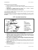
FM48/FM60/FM72 OPERATOR’S MANUAL 1 - GENERAL INFORMATION Thank you and congratulations for having chosen our implement. Your new grooming mower is a technologically advanced machine constructed of high quality sturdy components that will fulfill your working expectations. Read this manual carefully. It will instruct you on how to operate and service your mower safely and correctly. Failure to do so could result in personal injury and/or in equipment damage. 1.
FM48/FM60/FM72 OPERATOR’S MANUAL Warranty does not cover the following: 1. Cleaning, transporting, mailing and service call charges. 2. Normal wear items such as belts, blades, bearings, drivelines, shear pins, slip clutches, etc. 3. Depreciation or damage caused by normal wear, accidents, improper maintenance, improper protection or improper use. 4. The use of non original spare parts and accessories. Your Authorized Company Dealer has genuine parts in stock.
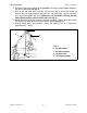
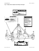
FM48/FM60/FM72 OPERATOR’S MANUAL 8. Bolt up the top hitch supports to the outside of the front support plates welded to the front of the deck (see fig. 2). 9. Bolt up the top hitch plate with the 16x150 mm. bolt. It should be bolted as follows: bolt, top hitch support, top hitch arm, top hitch plate, spacer, top hitch arm, top hitch support, lock nut. Tighten the lock nut down securely, the top hitch plate should be able to swivel 360° (see fig. 2). 10.
FM48/FM60/FM72 OPERATOR’S MANUAL 2 - SAFETY PRECAUTIONS Safety is the primary concern in the design and manufacture of our products. Unfortunately our efforts to provide safe equipment can be wiped out by a single careless act of an operator. In addition to the design and configuration of equipment, hazard control and accident prevention are dependent upon the awareness, concern, prudence and proper training of personnel involved in the operation, transport, maintenance and storage of equipment.
FM48/FM60/FM72 OPERATOR’S MANUAL 2.02 - Starting and Stopping 1. Be sure that no one is near the machine prior to engaging or while the machine is working. 2. Be sure the tractor is in "Neutral" before starting engine. 3. Mower operating power is supplied from tractor PTO. Refer to your tractor manual for PTO engagement and disengagement instructions. Always operate PTO at 540 rpm. Know how to stop the tractor and mower quickly in case of an emergency. 4.
FM48/FM60/FM72 OPERATOR’S MANUAL Fig. 4 - Safety Decals; Replace immediately if damaged.
FM48/FM60/FM72 OPERATOR’S MANUAL 3 - OPERATION You have purchased a three spindle mower designed especially for the mowing of grassy areas where a highly professional cut is required without wasting time. This mower is perfect for the maintenance of parks, private lawns, industrial parks, airports, hospital grounds, schools, highways, golf courses, sport complexes, etc. The grooming mower, for tractors up to 30 HP, come in working widths of 4’, 5' and 6'.
FM48/FM60/FM72 OPERATOR’S MANUAL rented to someone who has not read the operator's manual and is not familiar with a rotary mower. 5. Always stop the tractor, set brake, shut off the tractor engine, remove the ignition key, lower implement to the ground and allow mower blades to come to a complete stop before dismounting tractor. Never leave equipment unattended with the tractor running. 6. Never place hands or feet under mower with tractor engine running or before you are sure all motion has stopped.
FM48/FM60/FM72 OPERATOR’S MANUAL 21. Inspect the entire machine periodically1. Look for loose fasteners, worn or broken parts, and leaky or loose fittings. 22. Use only the driveline supplied with the mower. Do not use it if it is missing any shield or safety protection. 23. Pass diagonally through sharp dips and avoid sharp drops to prevent "hanging up" tractor and mower. 24. Avoid sudden starts and stops while traveling up or downhill. 25. Always cut down slopes; never across the face.
FM48/FM60/FM72 OPERATOR’S MANUAL 3.03 - Cutting Height Adjustment WARNING: Keep hands and feet away from moving blades. Be sure tractor engine is off, parking brake is locked, and key is removed before making any adjustments. Never rely on the tractor lift system. Install blocks or stands under the mower deck to prevent it from falling. Fig. 7 The cutting height is adjusted by moving the height adjustment spacers on the wheel yokes above or below the wheel arm.
FM48/FM60/FM72 OPERATOR’S MANUAL 3.04 - Pre-Operational Check Check each of the following, carefully, prior to engaging the equipment: 1. The spindle bearings have been greased. 2. The belts for proper tension. 3. The oil in the gearbox. 4. The driveline cross & bearings have been greased. 5. No wrappings or foreign objects are around the blades, belts or driveline. 6. The blades are properly installed and the blade bolts properly torqued3. 7. All hardware is tight. 8.
FM48/FM60/FM72 OPERATOR’S MANUAL To attach the mower to the tractor do the following: 1. Back the tractor up to the mower in order to slip the tractor hitch arms over the hitch pins welded to the mower hitch arms. Turn off the tractor engine. Secure them in place with the lynch pins. 2. Adjust the tractor sway blocks or chains to remove all side movement. 3. Attach the top link.
FM48/FM60/FM72 OPERATOR’S MANUAL 7. Checking to ensure that the cutting edge is the leading edge of the blade6. 8. Checking that there is no wire, weed, grass or other material wrapped around blades. 9. Checking to see if front weights need to be added to the tractor in order to maintain balance. 10. Checking the tractor tires for the proper pressure in accordance with the tractor operator's manual. 11.
FM48/FM60/FM72 OPERATOR’S MANUAL Always operate PTO at 540 rpm. This is necessary to maintain proper blade speed and obtain a clean cut. Under certain conditions, tractor tires may roll some grass down and prevent it from being cut at the same height as the surrounding area. If this occurs reduce the tractor ground speed but maintain a 540 rpm engine speed. The lower ground speed will permit the grass to at least partially rebound.
FM48/FM60/FM72 OPERATOR’S MANUAL 3.09 - Uneven Terrain DANGER: Be careful of rollover when operating tractor and mower over uneven ground. In extremely uneven terrain rear wheel weights, front tractor weights, and/or tire ballast should be used to improve stability. When mowing over uneven terrain, observe the type of terrain and develop a safe mowing pattern. Whenever traction or stability is doubtful, first test drive over the terrain with the PTO disengaged.
FM48/FM60/FM72 OPERATOR’S MANUAL 4 - MAINTENANCE DANGER: Stop engine, lock parking brake and remove key before performing any service or maintenance. Never rely on the tractor lift system. Install blocks or stands under the mower deck to prevent it from falling. Always use personal protection devices, such as glasses or gloves when performing maintenance. Keep fingers out of slots to prevent injury. 4.01 - Maintenance Safety 1. Good maintenance is your responsibility. 2.
FM48/FM60/FM72 OPERATOR’S MANUAL 14. Never replace hex bolts with less than grade five bolts unless otherwise specified, i.e., shear bolts8. 15. Where replacement parts are necessary for periodic maintenance and servicing, genuine replacement parts must be used to restore your equipment to original specifications. The company will not claim responsibility for use of unapproved parts and/or accessories and other damages as a result of their use. 16.
FM48/FM60/FM72 OPERATOR’S MANUAL same amount to the wheel arm grease fittings (see fig. 9). See the driveline manufacturer operator's manual for further information on the driveline. 2. Gearbox oil level: check gearbox oil level, it should be between 1/2 and 2/3 full. If needed add either SAE 90 wt. or SAE 140 wt. gear oil. Every 25 hours: check hardware tightness; mower vibrations can loosen bolts10. Check tightness of the hardware periodically, using this table as a guide. Every 50 hours: 1.
FM48/FM60/FM72 OPERATOR’S MANUAL Mower's spindle assembly. 1 2 3 4 5 6 7 8 9 Fig. 11 11 10 Ground 7. blade 8. cup washer 9. blade bolt 10. cutting edge close to ground 11. lift wing 1. grease fitting 2. hexagonal nut 3. pulley 4. rotor support 5. cover 6. shaft Removing or installing blades If the mower blades need to be removed, do the following: 1. The blade turns in a counter clockwise direction when viewed from the bottom of the deck.
FM48/FM60/FM72 OPERATOR’S MANUAL DANGER: Proper torque must be used when tightening the blade retaining bolt. If these safety precautions are not followed, the blade could come off during operation and be thrown hundreds of feet from the mower. 1 2 Fig. 12 1. spindle 2. blade 3. blade bolt 3 Sharpening Blades Blade sharpening is extremely important in order to get the best cutting results. Sharp blades permit a high quality cut and also reduces HP thus lowering cost.
FM48/FM60/FM72 OPERATOR’S MANUAL delivery, the spring is located in the first position. When the belt stretches after use, adjust the tension by relocating the spring in the other two holes. If the belt has stretched to the point that the belt is not tight enough even in the last hole it is necessary to replace the belt. 1 2 3 Fig. 13 1. tensioner 2. belt 3. pulley 4. spring 5. hitch plate 5 4 4.
FM48/FM60/FM72 OPERATOR’S MANUAL To replace the belt do the following: 1. Remove belt shields. Clean foreign material from the mower deck and belt area. 2. Release spring tensioner to loosen belt. 3. Loosen rear nuts holding central plate (do not remove them). 4. Remove front nuts holding central plate (see fig. 13). 5. Lift the front of the central plate and remove old belt. 6. Replace new belt starting from the right spindle pulley (see fig. 14). 7. Lower central plate. 8. Replace front nuts.
FM48/FM60/FM72 OPERATOR’S MANUAL In the collapsed position the driveline should be approximately 2" from bottoming out to prevent possible damage to the tractor or implement. When the PTO is in the maximum extended position, the ideal minimum overlap of the two halves should be approximately 6" (see fig. 15). If determined that the driveline is too long. Follow these procedures to adjust the length: 1. Separate the two driveline halves. Connect one half to the tractor PTO and the other half to the mower.
FM48/FM60/FM72 OPERATOR’S MANUAL Before transporting: 1. Disengage PTO. 2. Shorten tractor top link until top hitch plate is locked. 3. Raise machine and lock rock shaft control lever. 4. Always select a safe ground speed that is appropriate for the terrain. 5. Beware of traffic on public roads. Install a SMV (Slow Moving Vehicle) sign when traveling on roads or streets. 6. Reduce ground speed when turning and take care that the mower does not strike obstacles such as trees, fences or buildings.
FM48/FM60/FM72 OPERATOR’S MANUAL TABLE 1 - TORQUE SPECIFICATIONS Diameter Class 8.8 Class 10.9 N.m lb.ft N.m lb.ft M8 25 18 35 26 M 10 50 37 70 52 M 12 90 66 125 92 M 14 140 103 200 148 M 16 215 155 305 225 M 18 295 217 420 309 M 20 420 302 590 438 When using locks, nuts, increasing torque values by 5%. TABLE 2 - FINISHING MOWER - TECHNICAL FEATURES Rear Discharge, for tractors up to 30 HP, PTO 540 rpm, 3 point hitch cat.
FM48/FM60/FM72 OPERATOR’S MANUAL 5 - REPAIR PROCEDURES CAUTION: All repair procedures must be done by authorized dealerships. It is not recommended that untrained individuals perform any repair work. The following operations are detailed for qualified personnel only. 5.01 - Gearbox To remove the gearbox do the following: 1. Remove the belt12 (see fig. 13). 2. Remove the nut holding the pulley to the gearbox pinion shaft. 3. Remove the pulley. 4. Remove the nuts holding the gearbox to the central plate.
FM48/FM60/FM72 OPERATOR’S MANUAL Description Blades Blade bolts Washers Belts Quantity 3 3 3 1 5.04 - Storage After seasonal use it is important to perform the following for prolonged storage: 1. Wash the mower carefully. 2. Inspect the mower and replace worn or damaged parts. 3. Tighten all hardware. Grease all areas indicated under Maintenance15. 4. Loosen the belts if the mower is to be stored for an extended length of time. 5.
FM48/FM60/FM72 OPERATOR’S MANUAL 6 - TROUBLESHOOTING WARNING: Be sure tractor engine is off, parking brake is locked, and key is removed before making any adjustments. PROBLEM POSSIBLE CAUSE SOLUTION Uneven cutting. Cup washer not between blade and bolt. Ground speed too fast. Blades need sharpening. Caster wheels uneven Check washer location at all 3 spindles. Shift to lower gear. Sharpen blades. Adjust wheel position. Blades turning but not cutting. Direction of blades is wrong.
FM48/FM60/FM72 OPERATOR’S MANUAL 7 - PRE-DELIVERY CHECKLIST To the dealer: Inspect the machine thoroughly after assembly to assure it is functioning properly before delivering it to the customer. The following checklist is a reminder of points to cover. Check off each item as it is found satisfactory or after proper adjustment is made. Gearbox oil level. Guards and shield properly fastened. Lubrication of grease fittings. All hardware properly tightened.
9 - PARTS MANUAL Finishing Mower 48”, 60” & 72” FM48 FM60 FM72
FM48/FM60/FM72 PARTS MANUAL OPERATOR’S MANUAL 34 CUB CADET YANMAR
FM48/FM60/FM72 FRAME Ref.
FM48/FM60/FM72 PARTS MANUAL OPERATOR’S MANUAL 36 CUB CADET YANMAR
Ref.
FM48/FM60/FM72 PARTS MANUAL OPERATOR’S MANUAL 38 CUB CADET YANMAR
FM48/FM60/FM72 Ref. 32 33 34 35 36 PARTS MANUAL Part # 005-4422 009-1446 000-3144 000-1806 000-8526 000-8797 OPERATOR’S MANUAL Part Description Cotter Pin D. 2 (EC Only) Bolt TE 8 x 25 Spring Washer D. 8 Nut D. 8 Hard Tire Air Tire 39 Qty.
FM48/FM60/FM72 PARTS MANUAL OPERATOR’S MANUAL 40 CUB CADET YANMAR
FM48/FM60/FM72 OPERATOR’S MANUAL Ref.
FM48/FM60/FM72 PARTS MANUAL OPERATOR’S MANUAL 42 CUB CADET YANMAR
FM48/FM60/FM72 Ref.
FM48/FM60/FM72 PARTS MANUAL OPERATOR’S MANUAL 44 CUB CADET YANMAR
FM48/FM60/FM72 Ref.
FM48/FM60/FM72 PARTS MANUAL OPERATOR’S MANUAL 46 CUB CADET YANMAR
FM48/FM60/FM72 OPERATOR’S MANUAL Ref. Part # 1 2 3 4 5 6 7 8 9 10 11 12 13 14 15 16 17 18 001-0192 001-2149 000-8892 000-8609 000-6513 001-0727 000-8601 001-0173 005-6681 000-3038 000-1077 005-0192 002-5332 001-0196 003-4196 004-2122 000-2295 020-8430 030-8430 000-6688 000-8623 000-6698 000-8893 005-1187 001-5263 000-2034 003-0156 Oil Seal 40.68 .
FM48/FM60/FM72 PARTS MANUAL OPERATOR’S MANUAL 48 CUB CADET YANMAR
FM48/FM60/FM72 OPERATOR’S MANUAL Ref.
= Finishing Mower 48”, 60” & 72” FM48, FM60 & FM72=========== =============== Cub Cadet Yanmar LLC. P.O.