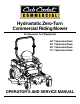
Hydrostatic Zero-Turn Commercial Riding Mower Professional Turf Equipment 48” Fabricated Deck 54” Fabricated Deck 60” Fabricated Deck 72” Fabricated Deck OPERATOR’S AND SERVICE MANUAL
TABLE OF CONTENTS Foreword. . . . . . . . . . . . . . . . . . . . . . . . . . . . . . . . . . . . . . . . . . . . . . . . . . . . . . . . . . . . . . . 3 General Safety Operations . . . . . . . . . . . . . . . . . . . . . . . . . . . . . . . . . . . . . . . . . . . . . . . . . 4 A.Danger . . . . . . . . . . . . . . . . . . . . . . . . . . . . . . . . . . . . . . . . . . . . . . . . . . . . . . . . . . 4 B. Warning . . . . . . . . . . . . . . . . . . . . . . . . . . . . . . . . . . . . . . . . . . . . . . .
FORWARD The Tank Hydrostatic Zero-Turn Commercial Riding Mower provides superb maneuverability, mid-mount cutting capability for professional landscapers, commercial lawn service companies, professional turf managers and golf course superintendents. The machine incorporates many safety features that should be studied by all operators and maintenance personnel before use. The list of safety precautions should receive particular attention.
GENERAL SAFETY OPERATIONS 6. Do not check for hydraulic leaks with any part of the body. 7. Do not add fuel to a machine when the engine is running and/or the exhaust system is hot. 8. Keep machine clean and free of debris, grass, leaves, oil, grease, etc. 9. Place lap bars in neutral/start position, set park brake, disengage P.T.O., turn engine off, and remove ignition key before you dismount from machine. 10. Use machines laterally or diagonally across slopes, avoid going downhill when possible. 11.
and battery surfaces kept clean of acids and corrosion. If batteries are re-charged or “jumped” from external sources, make sure that the connections are made properly and in the correct sequence...connect to the positive terminal of the good battery first, then connect that to the positive terminal of the weak battery. The third connection should be to the negative terminal of the good battery, followed by the negative terminal of the weak battery.
13. 14. 15. 16. condition and that the blade bolts are tight before restarting the engine. Never leave the mower unattended without: turning off the blade clutch switch; placing the left and right steering levers in the neutral position; moving the throttle to slow; setting the parking brake; shutting off the engine and taking the key from the ignition switch. Never walk or stand on the discharge side of a mower with the engine running.
8. 9. 10. 11. 12. counter-clockwise to decrease. Self-lubricating bearings are utilized throughout the suspension mechanism that provides an additional 2” of suspension travel. 4. A retractable seat belt assembly with inertialock is attached to the “ride” portion of the seat frame.
SAFETY DECALS AND LABELS TO REDUCE THE RISK OF INJURY, D O N OT O P E RAT E M OW E R U NL E S S DISCHARGE CHUTE COVERORGRASS C A T C H E R IS I N I T S P R O P E R P L A C E . WARNING SHIELD MISSING DO NOT OPERATE D AN GER K E E P H A N D S a n d FE E T A W A Y Part Number: 00030635 Part Number: 01002166 DANGER ROTATING BLADE Do not put hands or feet under or into mower when engine is running.
SPECIFICATIONS GENERAL INFO. Controls: Parking Brake: Seat: Frame: Instrumentation Front Caster Wheels: Drive Wheels: Tire Pressure: Fuel Tank: Ground Speed: Net Weight: ENGINE INFO. Engine: Type: Air Cleaner: Lube System: Hydraulic System: Starter: Blade Brake Clutch: Engine ignition and start switch; throttle; choke; left and right steering levers; electric blade clutch switch; parking brake; mower deck lift Mechanical linkage brake handle to internal drum brakes Adjustable seat and armrests.
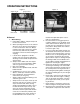
OPERATING INSTRUCTIONS Figure. 1 Engine throttle Choke Lever Figure. 2 Ignition Switch Electric Blade Clutch Switch Tach and Hour Meter Parking Brake A.General maintain the uphill side lap bar “essentially” in a fixed position. k. Be careful when crossing gravel paths or roadways. Always turn off the blade clutch switch and wait until the blades stop rotating and raise the cutting deck to the transport position. Always allow other vehicles to have the right of way. l.
of grease, grass, and leaves to reduce the chance of fire and permit proper cooling. Note: If low traction conditions occur, follow these procedures for “zero turns”: To turn clockwise (front of machine moves toward RIGHT) when traveling FORWARD: 1. Come to a stop, 2. Then slowly move both lap bars rearward (no more than 1/2 maximum reverse speed) to initiate REVERSE travel, 3. Then slowly move the LEFT lap bar forward while maintaining the RIGHT lap bar in the rearward travel position. 4.
Steering Levers Note: The 19hp and 23hp use the 5 gallon fuel tank. Figure. 4 Foot Pedal Lift Figure. 3 wheel, making the mower turn toward the side where the lever is behind. When one lever is pushed forward and the other lever pulled back the same amount, one traction wheel will turn in reverse and the mower will turn within its own length. In order to start the engine, both steering levers must be in the neutral position; the parking brake must be engaged; and the blade clutch switch must be “off”.
beneath the operator’s seat. Always wipe off the area around the oil tank fill neck before checking the oil level to prevent dirt from contaminating the oil. Remove the cap and make sure the oil level is a 1/4” below the oil tank fill neck. If the oil level is low, fill with Shell Rimula 15W40 or equivalent oil. Equivalent oil should meet GM Allison C-4. d. Tires: 8-10 psi Rear, 20-25 psi Front Caster Tires direction until it stops, it will shut off the flow of fuel to the engine.
fore-and-aft, as well as up-and-down — 9/16" wrench required). c. Become familiar with all of the machine controls, instrumentation, safety and instruction signs, and safety devices. d. Move (or have moved) the machine to a safe, level area with no obstructions including objects, pedestrians, and animals. 2. Initial Operation: a. Use protective equipment for eyes, hands, hearing, feet, legs, head and other areas of the body if needed — safety eye glasses, gloves, earplugs, boots, hats, etc. ure 5).
rotate and a “pivot turn” will be executed — turf defacement could occur (if on grass) as well as potential damages to the traction surface and the tire. If the lap bar on the turn side is not brought all the way to neutral, then the turn side tire will continue to rotate and a “U-turn” will be executed with a low potential for turf defacement as well as traction surface and tire damage. i. To drive in the REVERSE direction: 1. Make sure no bystanders, animals, or objects are behind the machine.
Release both lap bars and the machine should stop turning. 3. To turn counter-clockwise, slowly move the RIGHT lap bar forward while simultaneously moving the LEFT lap bar rearward. Release both lap bars and the machine should stop turning (this is a safety check, the normal procedure is for the operator to slowly bring the lap bars to the neutral position). 3. Start the Engine: a. Open the fuel shutoff valve. b. Sit on the Seat. Set the parking brake “On”. c.
Height of Cut Clevis Pin Main Frame Linch Pins Figure. 6 Linch Pins MAINTENANCE AND SERVICE adjacent blade (I.E., the blades do not need to be “timed” nor synchronized). Hi-lift- These are generally the best cutting blades for most grasses and mowing conditions. These blades will provide extra “lift” for the thinner leaf grasses, will handle lush grasses, and will provide maximum grass and debris discharge. These blades are generally required for material collection systems.
conventional electric grinder or a hand file to sharpen the blades. d. Replace any blade with severe nicks or dents that cannot be removed by filing. e. Check the balance of the blade after sharpening by placing it on a blade balancer. Do not use un-balanced blades. f. If the blade dips on one end, file stock off of the cutting surface on that end. Cover Plate Spindle Note: Blades that cannot be easily balanced—REPLACE. 4. Changing the Blade Drive Belts: a. Set the parking brake.
caps and drain oil from both left and right pumps. Replace and retighten nuts. Hydraulic pumps Figure. 8 1. Hydraulic Tank Figure. 9 Unfasten hose and drain from this side of both pumps. Adding Hydraulic Oil (use Rimula SAE15W40) Place the Mower on a level surface and engage the parking brake. b. Stop the engine and remove the key from the ignition switch. c. Clean the area around the Hydraulic Oil fill neck. d. Remove the hydraulic fill cap and check the level.
c. Store the battery with a full charge. A discharged battery will freeze (refer to the table below). Specific Gravity Freezing Temp (°F) 1.265 -71 1.250 -62 1.200 -16 1.150 5 1.100 16 d. Attach the other end of the black jumper cable to the frame of the unit with the low charge battery. 6. Fuses: There is one fuse located in the wiring between the ignition and start switch and other electrical components. This is a standard plug-in type automotive fuse rated at 7.5 amp. 7.
while the Mower is in operation. If the tire diameter is not equal between the two tires, the Mower will pull to one side. when slight contact with the feeler gage occurs. Engage the BBC (PTO Clutch) a couple of times, and re-check the air-gap. If it is not between the specs listed on page 22, repeat the adjustment procedure. b. Steering lever/Parking Brake Switch: Sit in the operator’s seat.
available from any auto supply store. Follow the directions on the can. If the leaks are larger than 1/16" diameter, the tire can be repaired with rubber plugs also available in a kit from any auto supply store. If the tire bead is damaged, a tube will have to be installed in the tire or the tire will have to be replaced. 2. Repair: The mower is equipped with drum brakes and will not normally require maintenance. If they are not working properly, please contact your service center. F.
for expansion. Start the engine and let it run at idle for about five minutes. Check the filter for leaks. Idling the engine and the pumps in this way will purge any air from the system. Shut off the engine and recheck the oil level in the tank. Top-off if necessary until the oil level is a 1/4” below the oil tank fill neck. feature with hydraulic dampers to provide smooth, non-jerkey, control motion while affording an automatic hydrostatic braking means.
i. Inspect the hydraulic hoses, lines and fittings. Replace as necessary. j. Jack the mower up and store it on blocks to take the weight off of the tires. 2. To Put the Mower Back in Service: a. Check the battery. Charge if necessary. b. Gasoline Engine Only: Remove the spark plugs and wipe them off. Using the starter, crank the engine to pump the excess oil out of the spark plug holes. Replace the spark plugs and the ignition leads. Refill the fuel tank with fresh gasoline. c.
MAINTENANCE SCHEDULE 7. D. Every 100 Hour Checks A. Daily Checks 1. 1. Before starting engine: a. Check the fuel level.** b. Check the engine oil level.** c. Check the hydraulic oil level. d. Check the hydraulic hoses for leaks, abrasion, kinks, twists, or a flattened condition. e. Check the tires and tire pressure. Drive Tires: 8-10 psi. Front Caster Wheels: 20-25 psi. f. Check the spindle belt, the mower drive belt and the hydro drive belt. g. Check the blades.
. OIL CHART Apply a few drops of engine oil or use a spray lubricant. Apply the oil to both sides of pivot points. Wipe off any excess. Start engine and operate mower briefly to insure that oil spreads evenly.
Performance Adjustments B. Engine RPM Check and Adjustment A. High Speed Tracking Adjustment If mower tracks to one side with both lap bars in fully forward position: 1. 2. 3. 4. 5. 6. High RPM Spec. Low RPM Spec. 23, & 25 Hp Kawasaki 3600 +/-50 1550 +/-100 27 HP Kohler 3600 +/-50 1550 +/-100 33 HP Generac 3600 +/-50 1550 +/-100 NOTE: RPM Specs. are for free running engines under no load. Check air pressure in all four tires: a.
g. Verify proper throttle adjustment by checking RPM readings as outlined above. b. 4. C. Deck Corner Ball Wheel Roller Settings Note: If lap bar adjustments are required, 1. Matching the set heights of the ball rollers on the four corners of the mower deck to the desired cut height will prevent edge scalping and minimize any side-to-side variance in cut height. 2. There are three height adjustment holes in the bracket that mount the ball rollers to the deck. a.
F. Deck leveling Procedure 1. 2. 3. 4. 5. 6. 7. aligned along the mower centerline. The bladeto-ground height at the rear of the blade tip should be 1/8" to 1/4” higher than the front tip. This is referred to as blade pitch. The sam height difference should be true for the left blade, measured front and back. 8. To adjust the blade pitch the deck pitch must be adjusted. Loosen the inner jam nuts at the rear of the horizontal threaded rods.
WIRING DIAGRAM GD: 02002824 30
MANUFACTURER’S LIMITED WARRANTY FOR CUB CADET COMMERCIAL TANK ZERO-TURN COMMERCIAL RIDING MOWER IMPORTANT: To obtain warranty coverage owner may be required present proof of purchase and applicable maintenance records to the servicing dealer. Please see the operator’s manual for information on required maintenance and service intervals. In addition, Cub Cadet may deny warranty coverage if the hour meter, or any part thereof, is altered, modified, disconnected or otherwise tampered with.