
Manual

5
SECTION 2: ASSEMBLING YOUR SNOW THROWER
NOTE: This Operator’s Manual covers several models.
Snow thrower features vary by model. Not all
features discussed in this manual are applicable to all
snow thrower models.
Unpacking
• Remove staples from the top, sides, and ends of
the shipping crate.
• Set panels aside to avoid tire punctures or personal
injury.
• Remove and discard plastic bag that covers unit.
• Roll the unit out of the crate.
• Check the crate thoroughly for loose parts before
discarding.
Loose Parts
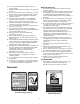
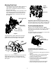
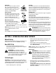
• The augers are secured to the auger shaft with four
shear pins (six for 45"augers)and bow-tie cotter
pins. If you hit a foreign object or ice jam, the snow
thrower is designed so that the pins may shear.
Two replacement shear pins and bow-tie cotter pins
are provided for your convenience. See Figure 1.
Store these safely until needed.
Figure 1
IMPORTANT:
NEVER replace the auger shear pins with
standard hex bolts. Any damage to the auger gearbox
or other components from using standard bolts will not
be covered by your snow thrower’s warranty.
Items Required For Assembly
1. Pair of pliers
2. Engine oil
3. Fresh gasoline
Before Assembly
WARNING: Disconnect the spark plug wire
and ground it against the engine to prevent
unintended starting.
NOTE: Reference to the right hand or left hand side of
machine are observed from the operating position.
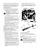
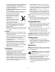
Assembling Handle
• Remove the lower plastic wing nut, belleville
washer and carriage bolt from each side of the
lower handle. See Figure 2.
• Raise the upper handle assembly until it snaps over
the lower handle.
• Looking beneath the handle panel, check that the
cables (steering, auger, and drive) are properly
routed and not pinched or kinked. Make certain the
springs at the lower end of the auger and drive
cables are securely hooked into their respective
actuator bracket.
Figure 2
• Secure the upper handle and lower handle with the
two plastic wing nuts, belleville washers and
carriage bolts removed earlier.
• Tighten the two wing nuts already installed in the
upper holes to firmly secure the upper handle and
support tubes.
• Align the upper and lower shift rods, then slide the
shift rod connector down over the end of the lower
shift rod. Tap the connector until it locks over the
lower shift rod. See Figure 2.
NOTE: If the connector is not properly assembled, the
shift rod will pivot and you will not be able to change
speeds or direction.
Bow-tie
Cotter Pin
Shear Pin
NOTE:
Support Tubes are omitted from the illustration for clarity.
Wing
Belleville
Carriage
Lower Handle
Upper Handle
Tighten these
Wing Nuts
Steering Cable
Cable Tie
Shift Rod
Connector
Upper
Lower
Shift
Nut
Washer
Bolt
Shift Rod
Rod