
Manual

6
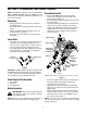
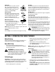
Attaching Chute Crank
• Remove the internal cotter pin from the upper chute
crank. Slide the upper chute crank through the
upper chute crank bracket and into the sleeve on
the lower chute crank.
• Align the hole in the upper chute crank with the hole
in the sleeve (If necessary, use a pair of pliers to
assist in aligning holes). Insert the internal cotter
pin through the holes to secure the chute crank.
See Figure 3.
Figure 3
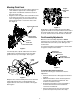
If not already done, slip the cables that run from the
handle panel to the discharge chute into the cable
guide located on top of the engine. See Figure 4.
Figure 4
Wrap the wire of the head lamp wire harness down the
right handle until the wire can be plugged into the
engine alternator wire connector down on the engine.
See Figure 5.
Figure 5
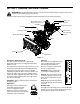
Normally the cable ties holding the steering cables
against the handle are loosely installed on each side of
the lower handle at the factory. Pull the cable ties tight
to secure. Cut the excess from the ends of cable ties.
Final Assembly Adjustments
Make these final assembly adjustments before
operating your snow thrower for the first time. Failure to
follow these instructions may cause damage to the
snow thrower.
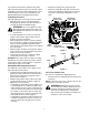
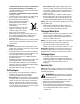
To test the wheel drive and auger drive controls, Refer
to Figure 6 and proceed as follows:
Figure 6
Testing Wheel Drive Control & Shift Lever
Perform the following test to determine need for
adjustment:
• Move the shift lever into sixth (6) position. Refer to
Figure 6.
• With the wheel drive control released, push the
snow thrower forward, then pull it back. The
machine should move freely.
• Engage the wheel drive control and attempt to
move the machine both forward and back,
resistance should be felt.
• Move the shift lever into the fast reverse (R2)
position and repeat the previous two steps.
Upper Chute Crank
Lower Chute Crank
Internal
Upper Chute
Crank Bracket
Cotter Pin
Cable
Discharge
Chute
Guide
Cable
Engine
Lamp Wire
Alternator
Lead
Wheel Drive
Control Released
Shift Lever
Auger Drive
Control Released