Professional Landscaping Tools BB40 BACK PACK BLOWER IMPORTANT: READ SAFETY RULES AND INSTRUCTIONS CAREFULLY DO NOT THROW AWAY
Table of Contents Content Page Introduction . . . . . . . . . . . . . . . . . . . . . . . . . . . . . . . . . . . . . . . . . . . . . . . . . . . . . . . . . . . . . . . 2 Safety . . . . . . . . . . . . . . . . . . . . . . . . . . . . . . . . . . . . . . . . . . . . . . . . . . . . . . . . . . . . . . . . . . . 3 Know Your Unit . . . . . . . . . . . . . . . . . . . . . . . . . . . . . . . . . . . . . . . . . . . . . . . . . . . . . . . . . . . . 7 Assembly . . . . . . . . . . . . . . . . . . . . . . . . . .
Section 1 Safety The purpose of safety symbols is to attract your attention to possible dangers. The safety symbols, and their explanations, deserve your careful attention and understanding. The safety warnings do not by themselves eliminate any danger. The instructions or warnings they give are not substitutes for proper accident prevention measures. SYMBOL MEANING SAFETY ALERT SYMBOL: Indicates danger, warning or caution. Attention is required in order to avoid serious personal injury.
Safety (continued) • Add fuel in a clean, well-ventilated outdoor area where there are no sparks or flames. Slowly remove the fuel cap only after stopping engine. Do not smoke while fueling or mixing fuel. Wipe up any spilled fuel from the unit immediately. • Do not operate the engine faster than the speed needed to do the job. Do not run the engine at high speed when not in use. • Move the unit at least 50 feet (15 m) from the fueling source and site before starting the engine. Do not smoke.
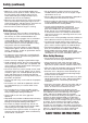
Safety (continued) PROTECTIVE SAFETY EQUIPMENT The Unit’s Protective Safety Equipment Personal Equipment Stop Switch- Use the stop switch to stop the engine. To service and test the stop switch, start the engine and make sure that the engine halts when you move the stop switch to the off position. Ear Protection- Wear ear protection that offers a sufficient dampening effect. Remove your hearing protection as soon as you stop the engine, in order to hear any noises or warning signals.
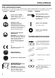
Safety (continued) Safety and International Symbols This operator's manual describes safety and international symbols and pictographs that may appear on this product. Read the operator's manual for complete safety, assembly, operating and maintenance and repair information. SYMBOL MEANING • SAFETY ALERT SYMBOL Indicates danger, warning, or caution. May be used in conjunction with other symbols or pictographs.
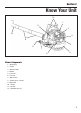
Section 2 Know Your Unit 12 1 11 2 10 3 9 4 8 7 6 5 Blower Components 1 - Spark plug 2 - Choke 3 - Starter handle 4 - Muffler 5 - Fuel tank 6 - Fuel cap 7 - Stop switch 8 - Throttle lever / control 9 - Blow tube 10 - Nozzle 11 - Air filter 12 - Shoulder Harness 7
Section 3 Assembly Instructions F A C B E D Assembling the Blower Carton Contents F - Engine Assembly Unpacking 1 - Hose Clamp with Screw (2) Your unit was carefully packed at the factory to prevent damage during shipment. Unpack the carton carefully: 1. Remove all contents from the carton. 2 - Flexible Tube 3 - Base Tube 4 - Middle Tube 2. Identify parts and check them with the list of parts in the above Carton Contents section. 5 - Bent Tube / Nozzle 3. Examine parts for damage. 4.
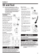
Section 4 Oil and Fuel NOTE: This unit is equipped with a 2-stroke engine that must always run on a mixture of gas and oil. It is important to measure the quantity accurately, to ensure the correct mixing ratio. Small discrepancies in the amount of oil have a great bearing on the fuel mix proportions when mixing a small amount of fuel. Oil and Fuel Mixing Instructions Old and/or improperly mixed fuel are the main reasons for the unit not running properly. Be sure to use fresh, clean unleaded fuel.
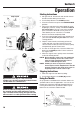
Section 5 Operation Starting Instructions Stop Switch 1. Mix gas with oil. Fill fuel tank with fuel/oil mixture. See Oil and Fuel Mixing Instructions. 2. Put the Stop Switch in the START position. 3. Place the choke lever up into the CHOKE/CLOSE position. 4. Fully press and release the primer bulb (air purge diaphragm) 10 times, slowly, until fuel is visible in the primer bulb. If you can’t see fuel in the bulb, press and release the bulb as many times as it takes before you can see fuel in it.
Operation (continued) Holding the Blower/Vacuum Before operating the unit, stand in the operating position. Check for the following: • Operator is wearing proper clothing, such as boots, safety glasses or goggles, ear/hearing protection, gloves, long pants and long sleeve shirt • Operate power equipment only at reasonable hours— not early in the morning or late at night when people might be disturbed. Comply with times listed in local ordinances.
Section 6 Maintenance To avoid serious personal injury, always turn your blower off and allow it to cool before you clean or service it. Always wear protective gloves during maintenance operations. Do not carry out maintenance when the engine is hot. Daily Maintenance Weekly Maintenance 1. Clean the unit’s exterior. 2. Check that the throttle control functions safely. 3. Check that the stop switch is functioning properly. 4. Clean the air filter. 5. Check that all the nuts and screws are tightened.
Maintenance (continued) Muffler Only start and use the unit when it is completely constructed. If you use the unit without all its covers fitted, you risk serious personal injury. Carburetor The unit’s engine is broken in after it has run through 8-10 tanks of fuel. To ensure the engine’s peak performance, you should have your engine serviced by an authorized dealer after it has been broken in. The service technician uses a revolution counter to adjust the carburetor for optimum operating conditions.
Maintenance (continued) Cooling System Air Filter To maintain as low of an operating temperature as possible, the engine is equipped with a cooling system. The cooling system consists of: 1. An air intake on the starter unit. The air filter should be cleaned regularly to remove dust and dirt. This will help avoid: • Carburetor malfunction 2. Cooling fins on the flywheel. 3. Cooling fins on the cylinder. 4. A cylinder cover that leads cold air onto the cylinder.
Section 11 Specifications ENGINE* Engine Type ........................................................................................................................... Air-Cooled, 2-Cycle Cylinder Capacity ..................................................................................................................................... 40.2 cm3 Cylinder Bore...............................................................................................................................................
MANUFACTURER’S LIMITED WARRANTY FOR: The limited warranty set forth below is given by Cub Cadet Commercial LLC with respect to new merchandise purchased and used in the United States, its possessions and territories. Cub Cadet Commercial LLC warrants this product against defects in material and workmanship for a period of two (2) years commencing on the date of original purchase and will, at its option, repair or replace, free of charge, any part found to be defective in material or workmanship.