OPERATOR’S MANUAL AutoDrive Lawn Tractor Model CLT 160 ™ IMPORTANT: READ SAFETY RULES AND INSTRUCTIONS CAREFULLY CADET, 60 OTTAWA STREET SOUTH, KITCHENER, ONT. N2G 3S7 PRINTED IN THE U.S.A.
SECTION 1: TABLE OF CONTENTS PAGE FINDING YOUR MODEL NUMBER . . . . . . . . . . . . . . . . . . . . . . . . . . . . . . . . . . . . . . . . . . . . . . . . . . . . . . . 2 CALLING CUSTOMER SUPPORT . . . . . . . . . . . . . . . . . . . . . . . . . . . . . . . . . . . . . . . . . . . . . . . . . . . . . . . 2 IMPORTANT SAFE OPERATION PRACTICES . . . . . . . . . . . . . . . . . . . . . . . . . . . . . . . . . . . . . . . . . . . . . 3 SAFETY LABLES FOUND ON YOUR UNIT . . . . . . . . . . . . . . . . . . . . . .
SECTION 4: IMPORTANT SAFE OPERATION PRACTICES WARNING: This symbol points out important safety instructions which, if not followed, could endanger the personal safety and/or property of yourself and others. Read and follow all instructions in this manual before attempting to operate this machine. Failure to comply with these instructions may result in personal injury. When you see this symbol—heed its warning.
6. Keep all movement on the slopes slow and gradual. Do not make sudden changes in speed or direction. Rapid engagement or braking could cause the front of the machine to lift and rapidly flip over backwards which could cause serious injury. 7. Avoid starting or stopping on a slope. If tires lose traction, disengage the blade(s) and proceed slowly straight down the slope. 25. Disengage all attachment clutches, depress the brake pedal completely and shift into neutral before attempting to start engine. 26.
h. Never over fill fuel tank. Fill tank to no more than ½ inch below bottom of filler neck to allow space for fuel expansion. i. Replace gasoline cap and tighten securely. j. If gasoline is spilled, wipe it off the engine and equipment. Move unit to another area. Wait 5 minutes before starting the engine. k. To reduce fire hazards, keep machine free of grass, leaves, or other debris build-up. Clean up oil or fuel spillage and remove any fuel soaked debris. l.
nal equipment specifications may lead to improper performance and compromise safety!” 12. Do not change the engine governor settings or over-speed the engine. The governor controls the maximum safe operating speed of the engine. 13. Maintain or replace safety and instruction labels, as necessary. 14. Observe proper disposal laws and regulations for gas, oil, etc. to protect the environment. 10. Never attempt to make adjustments or repairs to the machine while the engine is running. 11.
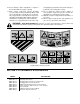
SECTION 6: SLOPE GAUGE D R EPR E S ENT ING A 1 5 ° SL OPE OR A FENCE POST A CORNER OF A BUILDING A POWER POLE SIGHT AND HOLD THIS LEVEL WITH A VERTICAL TREE USE THIS PAGE AS A GUIDE TO DETERMINE SLOPES WHERE YOU MAY NOT OPERATE SAFELY. FOL D ON O T T ED L INE, 15° WARNING Do not mow on inclines with a slope in excess of 15 degrees (a rise of approximately 2-1/2 feet every 10 feet). A riding mower could overturn and cause serious injury.
SECTION 7: TRACTOR SET-UP NOTE: Reference to RIGHT or LEFT side of the tractor in this manual is observed from operator’s position. ATTACHING THE STEERING WHEEL In the event your tractor was crated with the steering wheel and the seat removed for shipping reasons, use the following instructions to properly assemble the parts. ATTACHING THE BATTERY CABLES NOTE: The battery cables may or may not be WARNING: Do NOT operate the tractor attached on your unit.
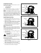
ATTACHING THE SEAT Standard Adjustment Seat styles vary by tractor model and there are three different styles available: • • • Hex Screws Standard Adjustment Quick Adjustment Knob Adjustment Shoulder Screws Refer to Figure 3, Figure 4 and Figure 5 to identify your tractor’s seat style and follow applicable instructions.
GAS AND OIL FILL-UP WARNING: The mowing deck is capable of The gasoline tank is located under the hood and has a capacity of either two or three gallons. Do not overfill. throwing objects. Failure to operate the riding mower without the discharge cover in the proper operating position could result in serious personal injury and/or property damage. WARNING: Use extreme care when handling gasoline. Gasoline is extremely flammable and the vapors are explosive.
SECTION 8: CONTROLS A* F B G A* H I + 1/10 P P J K C D L M E NOTE: NOTE: Steering Wheel not shown for clarity. Style varies by model.
IGNITION SWITCH THROTTLE CONTROL LEVER The throttle control lever is located on the right side of the tractor’s dash panel. This lever controls the speed of the engine and, on some models, when pushed all the way forward, the choke control also. When set in a given position, the throttle will maintain a uniform engine speed. See Figure 8. Choke Position WARNING: Never leave a running machine unattended.
SYSTEMS INDICATOR MONITOR / HOUR METER ELECTRIC PTO (POWER TAKE-OFF) KNOB Your tractor is equipped with either an hour meter or an ammeter as part of two available system indicator monitors. Locate the monitor on the left side of your dash panel and compare it to both shown in Figure 10. To engage the power to the cutting deck or other (separately available) attachments on models so equipped with an electric PTO, pull outward on the PTO knob.
SHIFT LEVER The shift lever is located on the left side of the fender and has three positions, FORWARD, NEUTRAL and REVERSE. The brake pedal must be depressed and the tractor must not be in motion when the moving shift lever. N NOTE: Cruise control can NOT be engaged at the tractor’s fastest ground speed. If the operator should attempt to do so, the tractor will automatically decelerate to the fastest optimal mowing ground speed. Shift Knob IMPORTANT: Never force the shift lever.
IMPORTANT: Do NOT hold the key in the START WARNING position for longer than ten seconds at a time. Doing so may cause damage to your engine’s electric starter. AVOID SERIOUS INJURY OR DEATH • • • • • • • • • • • • NOTE: If starting problems are encountered, refer to the TROUBLESHOOTING section of this manual. GO UP AND DOWN SLOPES, NOT ACROSS. AVOID SUDDEN TURNS. DO NOT OPERATE THE UNIT WHERE IT COULD SLIP OR TIP. IF MACHINE STOPS GOING UPHILL, STOP BLADE(S) AND BACK DOWNHILL SLOWLY.
ENGAGING THE PARKING BRAKE Disengage the cruise control using one of the following methods: To engage the parking brake: • • • • Fully depress the brake pedal and hold it there while gently pushing the parking brake button inward. Hold the parking brake button in while removing your foot from the brake pedal. Once engaged, the parking brake button and the brake pedal will lock in the “down” position. • To disengage the parking brake: • Lightly depress either the brake pedal or the drive pedal.
IMPORTANT: The engine or electric PTO clutch will automatically shut off if the PTO is engaged with the drive pedal in position for reverse travel. Refer to SAFETY INTERLOCK SWITCHES earlier in this section. • Keep the blades sharp and replace the blades when worn. Refer to the SERVICE section of this manual for proper blade sharpening instructions.
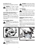
SECTION 10: MAKING ADJUSTMENTS WARNING: Never attempt to make any adjustments while the engine is running, except where specified in the operator’s manual. The front of the deck should be between 1/4-inch and 3/8-inch lower than the rear of the deck. Adjust if necessary as follows: • WARNING: Disconnect the spark plug wire(s) and ground against the engine before performing any adjustments, repairs or maintenance.
Quick-Adjust Seat (if so equipped) To adjust the position of the seat, move the seat adjustment lever to the left and slide the seat forward or rearward. Make sure seat is locked into position before operating the tractor. See Figure 14. Knobs Seat Seat Adjustment Lever Figure 16 Figure 14 CARBURETOR ADJUSTMENT Standard Seat To adjust the position of the seat on models not equipped with a seat adjustment lever, loosen, but do NOT remove the four screws which secure the seat to the seat pivot bracket.
Hex Nut Hex Nut and Lock Washer Zerk Fitting (if so equipped) Pivot Bar Axle Set Gap at 0.011" Brake Disc Drag Link Compression Spring NOTE: View shown from beneath tractor. Jam Nut Ball Joint Transmission Figure 18 Figure 17 NOTE: Threading the ball joints too far onto the drag links will cause the front tires to "toe-in" too far. Proper toe-in is between 1/16" and 5/16".
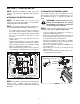
• • • • Water Port Hose Coupler (Shown without Hose Attached) • Figure 19 Pop open the protective cap on the end of the oil drain valve to expose the oil drain port. See Figure 20. Push oil drain hose (packed with unit) onto the oil drain port. Route the opposite end of the hose into an appropriate oil collection container with a capacity great enough to collect the used oil. Push the oil drain valve in slightly, then rotate counterclockwise and pull outward to begin draining oil. See Figure 20.
Front Wheels Rear Wheels Each of the front wheel axles is equipped with a grease fitting. Lubricate with a grease gun after every 25 hours of tractor operation. The rear wheels should be removed from the axles once a season. Lubricate the axles and the rims well with an all-purpose grease before re-installing them. SECTION 13: SERVICE TIRES • Place a block of wood between the center deck housing baffle and the cutting blade to act as a stabilizer. See Figure 21.
BATTERY • The battery is sealed and is maintenance-free. Acid levels cannot be checked Connect the other jumper cable to the negative terminal of the good battery, then to the frame of the unit with the dead battery. WARNING: Failure to use this procedure WARNING: Shield eyes (e.g. goggles, face could cause sparking, and the gas in either battery could explode. shield) and protect skin and clothing when handling battery acid or a battery containing acid.
CUTTING DECK REMOVAL All belts on your tractor are subject to wear and should be replaced if any signs of wear are present. To properly remove the cutting deck, proceed as follows: • • IMPORTANT: The V-belts found on your tractor are specially designed to engage and disengage safely. A substitute (non-OEM) V-belt can be dangerous by not disengaging completely. For a proper working machine, use factory approved belts. Place the PTO knob in the disengaged (OFF) position and engage the parking brake.
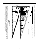
Models with Manual PTO Engine Pulley PTO Idler Bracket (mounted on tractor) Left Hand Pulley Deck belt (Bottom) PTO belt (Top) Right Hand Pulley (beneath belt guard) Deck Idler Pulley Center Pulley NOTE: Left hand belt cover not shown for clarity.
Variable-speed Pulley Battery Tray Opening Drive belt (Lower) Shift Lever Rear Idler Pulley Belt Keeper Drive belt (Upper) Electric PTO Clutch (if so equipped) Front Idler Pulley Idler Bracket Belt Keeper to AutoDrive pedal ™ Double-Idler Bracket Engine Pulley (Upper Portion) Transmission Idler Pulley Single-speed Transmission NOTE: Transmission Pulley Front of Tractor View shown from above tractor. Figure 27 • • • • • Locate the variable-speed pulley through the battery tray opening.
• • • • • Remove both hairpin clips from the pin which is fastened to the speed control assembly (be careful not to lose the small flat washers found on the pin). See Figure 29. Remove the drive pedal return spring. Using two 9/16" wrenches, remove the pin from the speed control assembly. See Figure 29. Thread the idler adjustment rod inward or outward to lengthen or shorten the travel of the double-idler bracket until proper adjustment is achieved.
SECTION 15: TROUBLESHOOTING Trouble Possible Cause(s) Corrective Action Engine fails to start PTO lever engaged. Parking brake not engaged. Spark plug wire(s) disconnected. Throttle control not in correct position Choke not activated Fuel tank empty, or stale fuel. Blocked fuel line. Faulty spark plug. Engine flooded. Place PTO lever in disengaged (OFF) position. Engage parking brake. Connect wire(s) to spark plug. Place throttle lever to CHOKE (if so equipped). Activate choke.
THREE (3) YEAR LIMITED WARRANTY For three (3) years from the date of original purchase of our products, we will either repair or replace, at its option, free of charge, F.O.B. Factory or authorized service firm, any part found to be DEFECTIVE IN MATERIAL and WORKMANSHIP for the original purchaser. all transportation charges on parts submitted for replacement under this warranty must be paid by the purchaser unless return is requested by the manufacturer.