Safe Operation Practices • Set-Up • Operation • Maintenance • Service • Troubleshooting • Warranty Operator’s Manual 33” Wide Cut Mower — CC 800 WARNING READ AND FOLLOW ALL SAFETY RULES AND INSTRUCTIONS IN THIS MANUAL BEFORE ATTEMPTING TO OPERATE THIS MACHINE. FAILURE TO COMPLY WITH THESE INSTRUCTIONS MAY RESULT IN PERSONAL INJURY. CUB CADET LLC, P.O. BOX 361131 CLEVELAND, OHIO 44136-0019 Form No.
1 To The Owner Thank You Thank you for purchasing a Lawn Mower manufactured by Cub Cadet. It was carefully engineered to provide excellent performance when properly operated and maintained. If applicable, the power testing information used to establish the power rating of the engine equipped on this machine can be found at www.opei.org or the engine manufacturer’s web site. Please read this entire manual prior to operating the equipment.
Important Safe Operation Practices 2 WARNING: This symbol points out important safety instructions which, if not followed, could endanger the personal safety and/or property of yourself and others. Read and follow all instructions in this manual before attempting to operate this machine. Failure to comply with these instructions may result in personal injury. When you see this symbol.
12. A missing or damaged discharge cover can cause blade contact or thrown object injuries. 13. Many injuries occur as a result of the mower being pulled over the foot during a fall caused by slipping or tripping. Do not hold on to the mower if you are falling; release the handle immediately. 14. a. Step back from mower to fully extend your arms. b. Be sure you are well balanced with sure footing. c. Pull the mower back slowly, no more than half way toward you. d. Repeat these steps as needed.
6. 7. Never allow children under 14 years of age to operate this machine. Children 14 and over should read and understand the instructions and safe operation practices in this manual and on the machine and be trained and supervised by an adult. After stopping engine, remove Electric Start Push Key (if equipped) and keep it in a safe place out of the reach of children. Service Safe Handling Of Gasoline: 1. To avoid personal injury or property damage use extreme care in handling gasoline.
Do not modify engine To avoid serious injury or death, do not modify engine in any way. Tampering with the governor setting can lead to a runaway engine and cause it to operate at unsafe speeds. Never tamper with factory setting of engine governor.
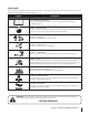
Safety Symbols This page depicts and describes safety symbols that may appear on this product. Read, understand, and follow all instructions on the machine before attempting to assemble and operate. Symbol Description READ THE OPERATOR’S MANUAL(S) Read, understand, and follow all instructions in the manual(s) before attempting to assemble and operate. DANGER — ROTATING BLADES To reduce the risk of injury, keep hands and feet away.
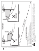
Section 2 — Important Safe Operation Practices Figure 1 line Figure 2 (TOO STEEP) 15° Slope WARNING! Slopes are a major factor related to slip and fall accidents which can result in severe injury or death. The machine is heavy and can speed up when going downhill. Be prepared to maintain control of the machine. To avoid loss of control, operate across slopes, not up and down. When turning, turn uphill, not down. Do not operate machine on slopes in excess of 15 degrees.
3 Assembly & Set-Up Contents of Crate • Lawn Mower (1) • Oil Drain Hose (1) • • Lawn Mower Operator’s Manual (1) • Engine Operator’s Manual (1) Key (1) Mower Set-Up Attaching the Battery Cables Shipping Brace Removal NOTE: The positive battery terminal is marked Pos. (+). The negative battery terminal is marked Neg. (–). WARNING! Make sure the lawn mower’s engine is OFF. Remove the ignition key (if equipped) before removing the shipping brace. 1. 1.
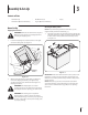
Unfolding the Handle 1. Remove the star knobs (a) and carriage screws (b) from the lower handle. See Figure 3-3. (c) (a) (d) (b) Figure 3-5 Figure 3-3 2. 2. Remove the remaining screw (c) and nut (d) from the lower shift lever plate. See Figure 3-5. 3. Position the upper shift lever into a vertical position aligning the holes in the lever with the holes in the shift plate. See Figure 3-6. Pivot the upper handle into operating position. Be careful not to crimp cables. See Figure 3-4.
4 Controls and Features Throttle Control Blade Control Fuel Tank Cap Ignition Switch† Deck Height Lever LCD Service Minder and Hour Meter† Drive Control Gear Shift Lever † If Equipped Figure 4-1 Lawn Mower controls and features are illustrated in Figure 4-1 and described on the following pages. WARNING! Read and follow all safety rules and instructions in this manual, including the entire Operation section, before attempting to operate this machine.
Ignition Switch Blade Control WARNING! Never leave a running machine unattended. Always disengage blades, stop engine and remove key to prevent unintended starting. Located on the right-hand handle, the blade control is used to engage the mowing deck. To operate, press and hold the lever against the handlebar grip. To stop the blades, release the blade control. WARNING! Never attempt to start the engine with the blade control engaged.
LCD Service Minder and Hour Meter Change Oil (If Equiped) The LCD will display the letters “CHG”, followed by the letters “OIL”, followed by the letters “SOON”, then finally followed by the meter’s accumulated time. “CHG/OIL/SOON/TIME” will alternate on the display for seven minutes after the meter reaches 50 hours. This oil service minder interval will occur every 50 hours for the following two hours.
5 Operation Gas and Oil Recoil Start Kit The fuel tank has a capacity of two gallons. Remove the fuel cap by turning it counter-clockwise. Use only clean, fresh (no more than 30 days old), unleaded gasoline. Fill the tank no higher than four inches below the top of the filler neck to allow space for fuel expansion. Refer to page 14 in the Set-Up and Assembly section of this manual for gasoline and oil fill-up instructions. WARNING! Use extreme care when handling gasoline.
Engaging the Drive WARNING! Avoid sudden starts, excessive speed and sudden stops. 1. Start the engine as instructed earlier in this section and move the throttle/choke control into the FAST (rabbit) position. 2. To travel FORWARD: a. b. Place the gear shift lever in any of the four Forward ground speeds. Select a speed appropriate for the conditions and a pace you’re comfortable with. Slowly squeeze the drive control against the left handle grip and the mower will move.
Mowing Installing / Removing Mulch Baffle WARNING! Before installing or removing the mulch plug, disengage blades, stop the engine and remove key (if equipped) to prevent unintended starting. The following information will be helpful when operating your mower. WARNING! Plan your mowing pattern to avoid discharge of materials toward roads, sidewalks, bystanders and the like.
6 Maintenance & Adjustments Maintenance Schedule Each use or every 5-10 Hours Clean Mower Check Engine Oil Level Check Air Filter Every 10 Hours Every season Every season Every season or or or 25 Hours 50 Hours 100 Hours P P P P P Replace Air Filter Element † P Change Engine Oil †† P Clean Battery Terminals P P P Clean Engine Cooling Fins Clean Finger Guard and around Muffler Prior to Storing P P Lube Front Wheels and Casters Lube Pivot Points P P P P Check Blade Timing Belt Check Spark
Maintenance 4. Pop open the protective cap on the end of the oil drain valve to expose the drain port. See Figure 6-2. 5. Remove the oil fill cap/dipstick from the oil fill tube. See Figure 6-1. 6. Push the oil drain hose provided onto the oil drain port. Route the opposite end of the hose into an appropriate oil collection container with at least a 2.5 quart capacity, to collect the used oil. 7.
Tire Pressure Air Cleaner The air cleaner element should be replaced every 100 hours or once a season. Service the pre-cleaner and cartridge/air cleaner element as instructed in the Engine Operator’s Manual. WARNING! Under any circumstance do not exceed manufacturer’s recommended psi. Equal tire pressure should be maintained at all times. Refer to sidewall of tire for recommended pressure. Spark Plug The spark plug should be cleaned and the gap reset every 25 hours or once a season.
3. Attach garden hose with the deck wash nozzle to the water port on your deck’s surface. See Figure 6-3. Lubrication WARNING! Before lubricating, repairing, or inspecting, always disengage PTO, set parking brake, stop engine and remove key (if equipped) to prevent unintended starting. Pivot Points & Linkage Lubricate all the pivot points on the drive system and lift linkage at least once a season with light oil. Rear Wheels The rear wheels should be removed from the axles once a season.
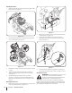
Blade Timing Belt 3. The cutting deck spindles are driven by a blade timing (cogged) belt, assuring that the deck blades are always perpendicular to each other. At least once a season, or after striking any foreign object, check the timing belt as follows: 1. Remove the belt cover by removing the three screws (a) and washers (b) which secure it to the frame. See Figure 6-5.
7 Service Cutting Deck Removal WARNING! Before performing any maintenance or repairs, disengage blades, stop engine and remove key (if equipped) to prevent unintended starting. To remove the cutting deck, proceed as follows: 1. Remove the belt cover by removing the three screws (a) and washers (b) which secure it to the frame. See Figure 7-1. (a) WARNING: Do not operate mower without the (b) belt cover installed. Failure to follow this instruction could result in personal injury or property damage.
10. Carefully unhook the mower’s lift assembly from the rear deck supports. 11. Use the deck height lever to raise the lift assembly to its highest position. 12. Remove the wooden blocks from under the deck and gently slide the cutting deck toward the rear of the machine. 13. Pull the click pin (a) out and unhook the drive spring cable from the idler arm assembly. See Figure 7-4. 2. Place a block of wood between the center deck housing baffle and the cutting blade to act as a stabilizer.
WARNING! A poorly balanced blade will cause excessive vibration, may damage the mower and/or result in personal injury. 5. Battery CALIFORNIA PROPOSITION 65 WARNING: Battery posts, terminals, and related accessories contain lead and lead compounds, chemicals known to the State of California to cause cancer and reproductive harm. Wash hands after handling. Test the blade’s balance using a blade balancer. Grind metal from the heavy side until it balances evenly.
Changing the Deck Engagement Belt Changing the Deck Timing Belt WARNING! Shut the engine OFF and remove key (if equipped) before removing the cutting blade(s) for sharpening or replacement. Protect your hands by using heavy gloves when grasping blades and pulleys. Several components must be removed and special tools used in order to change the mower deck’s timing belt. See your Cub Cadet dealer to have the deck’s timing belt replaced.
8 Troubleshooting Problem Engine fails to start Remedy 1. Fuel tank empty, or stale fuel. 1. Fill tank with clean, fresh (less than 30 days old) gas. 2. Blocked fuel line. 2. Clean fuel line and replace fuel filter. Refer to Engine Operator’s Manual. 3. Faulty spark plug. 3. Clean, adjust gap or replace plug. Refer to Engine Operator’s Manual. 4. Engine flooded. 4. Crank engine with throttle in FAST position. 5. Dead battery (Electric and Pull Start). 5. Recharge battery.
9 Replacement Parts Component Part Number and Description 951-10292 Spark Plug 937-05129 Air Filter Assembly (Includes Pre-Filter) 951-12182 Fuel Cap 951-3013 Fuel Filter 951-12690 Oil Filter 954-04139 Belt (Mowing Deck Engagement) 942-04154A Deck Blade Phone (800) 965-4CUB to order replacement parts or a complete Parts Manual (have your full model number and serial number ready). Parts Manual downloads are also available free of charge at www.cubcadet.com.
Component Part Number and Description 734-04263 634-04349 Wheel (Front) Wheel (Rear) 925-1707D† Battery 946-04604 Throttle/Choke Control (Cable) 925-2054A† Ignition Key 931-04244 Discharge Chute Assembly 631-04252 Mulch Baffle 731-05766 Trail Shield † If Equipped Phone (800) 965-4CUB to order replacement parts or a complete Parts Manual (have your full model number and serial number ready). Parts Manual downloads are also available free of charge at www.cubcadet.com.
10 Attachments & Accessories The following attachments and accessories are compatible for the Cub Cadet Wide Cut Mower. See your Cub Cadet dealer or the retailer from which you purchased your mower for information regarding price and availability.
FEDERAL and/or CALIFORNIA EMISSION CONTROL WARRANTY STATEMENT YOUR WARRANTY RIGHTS AND OBLIGATIONS MTD Consumer Group Inc, the United States Environmental Protection Agency (EPA), and for those products certified for sale in the state of California, the California Air Resources Board (CARB) are pleased to explain the evaporative emission control system (ECS) warranty on your 2016-2017 small off-road equipment (outdoor equipment).
WARRANTED PARTS: The repair or replacement of any warranted part otherwise eligible for warranty coverage may be excluded from such warranty coverage if MTD Consumer Group Inc demonstrates that the outdoor equipment has been abused, neglected, or improperly maintained, and that such abuse, neglect, or improper maintenance was the direct cause of the need for repair or replacement of the part.
CUB CADET LLC MANUFACTURER’S LIMITED WARRANTY FOR 33-INCH WIDE CUT MOWER IMPORTANT: To obtain warranty coverage owner must present an original proof of purchase and applicable maintenance records to the servicing dealer. Please see the operator’s manual for information on required maintenance and service intervals.