Illustrated Parts Manual Fall / Winter Chore Performers CUB CADET LLC, P.O. BOX 361131 CLEVELAND, OHIO 44136-0019 Printed In USA Form No.
To The Owner Thank You Thank you for purchasing a Chore Performer. It was carefully engineered to provide excellent performance when properly operated and maintained. All information in this manual is relative to the most recent product information available at the time of printing. Please be aware that this Illustrated Part’s Manual may cover a range of product specifications for various models. Components listed and/or illustrated in this manual may not be applicable to all models.
Page Left Blank Intentionally 3
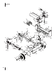
LS 27 CC A 22 76 6 23 79 40 13 2 5 60 4 1 11 68 7 8 19 12 63 75 74 3 9 18 15 77 54 B 42 40 41 64 41 44 53 61 54 62 49 45 51 50 21 81 58 39 31 24 25 41 70 61 33 73 78 43 59 17 26 27 38 35 66 30 28 37 14 72 4 76 34 23 41 44 83 82 47 46 32 84 65 55 57 A 20 56 22 71 44 80 52 48 41 80 67 B 10 65 69 29 36 16
LS 27 CC Ref. Part Number Description Ref. Part Number Description 1 918-04713 Hydraulic Cylinder 38 732-0583 Compression Spring 2 727-04362 Hydraulic Tube 39 781-04293 Log Tray Bracket 3 710-1018 Hex Cap Screw, 1⁄2-20 x 2.75 40 710-04484 Hex Washer Screw, 5⁄16-18 x .
LS 27 CC Ref. 6 Part Number Description 77 781-0538A Hose Guard, 48” 78 710-04683A Sems Screw, 3⁄8-16 x 1.00 79 781-04418 Outer Valve Bracket 80 941-0475 Plastic Bushing, .380 ID 81 718-04392 Coupling, .500 82 735-04103 Spider Bushing 83 710-1842A Set Screws 84 710-0157 Hex Cap Screw, 5/16-24 x .
Page Left Blank Intentionally 7
LS 25 CC A 22 76 6 23 47 40 13 2 5 60 4 1 11 68 7 8 19 12 63 75 74 3 9 18 15 77 54 B 41 64 41 44 61 62 41 72 67 65 58 C 70 41 44 23 D 33 39 31 24 25 41 17 21 76 34 23 51 71 44 72 A 20 56 22 55 57 61 73 66 29 43 59 18 46 73 26 27 30 50 73 28 D 78 48 79 80 32 B 37 38 77 35 54 53 C 45 78 49 8 14 59 51 81 A 48 23 36 16 10 65 69 42 40 52
LS 25 CC Ref. Part Number Description Ref. Part Number Description 1 918-04713 Hydraulic Cylinder 41 712-04065 Flange Lock Nut, 3⁄8-16 2 727-04362 Hydraulic Tube 42 781-04179 Log Tray 3 710-1018 Hex Cap Screw, 1⁄2-20 x 2.75 43 681-04131 Frame Assembly 4 737-04320 90 Degree Solid Adapter 44 710-0521 Hex Bolt, 3⁄8-16 x 3 5 918-04740 Control Valve 45 719-0353 Coupling Shield 6 737-04307 Return Elbow 46 914-0122 Square Key, 3⁄16” x .
JS 1150 16 6 20 35 29 28 23 32 37 27 36 21 34 17 26 30 22 31 5 33 16 8 18 15 30 4 19 37 1 4 16 12 13 3 2 38 7 40 43 47 48 10 24 40 45 44 46 42 41 48 47 11 13 25 14 9 10 39 10 12
JS 1150 Ref. Part Number Description Ref. Part Number Description 1 681-04086 Lower Handle Assembly 26 712-04063 Flange Lock Nut, 5⁄16-18 2 710-04605 Hex Screw, 5⁄16-18 x 1.50 27 781-04181 Louver Lever 3 710-0487 Carriage Screw, 5⁄16-18 x 2.00 28 710-0237 Hex Bolt, 5⁄16-24 x .625 4 720-04072A Star Knob, 5⁄16-18 29 710-3008 Hex Bolt, 5⁄16-18 x .75 5 720-04091 Foam Grip, .
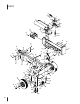
CS Model Series 410 & 420 36 40 14 35 34 41 37 27 18 3 6 1 29 5 9 12 A 11 13 10 2 4 8 7 31 22 2 31 7 4 28 18 20 21 33 32 19 B 16 17 23 39 41 15 41 24 42 25 41 42 26 B 18 12 43 A 38 30 18 18 32 34 40
CS Model Series 410 & 420 Ref No. Part Number Description Ref No. Part Number Description 1 981-04094 Impeller Assembly Complete 23 749-04103 Hopper Handle 2 710-1054 Machine Screw, 5/16-24 x 1.0 24 781-04007 Shredder Plate 3 738-04286A Shoulder Pin, .5 x 2.
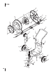
CS Model Series 410 & 420 35 18 38 20 25 16 A 37 9 22 15 20 17 19 5 14 14 13 36 24 11 12 7 23 21 A 28 3 14 13 8 2 7 26 34 30 26 38 33 29 31 32 21 27 14 1 4 6 10 20 39
CS Model Series 410 & 420 Ref No. Part Number Description Ref No. Part Number Description 1 981-0133 Tongue Hitch Mount 23 749-1004† Chipper Chute Support 2 681-0134A Base Hitch Mount 24 981-04032† Chipper Chute Hinge 3 710-3001 Hex Cap Screw, 3/8-16 x.88 25 781-0633† Chute Flap Strip 4 711-0299 Clevis Pin,.625 x 2.4 26 710-0805 Hex Cap Screw, 5/16-18 x 1.50 5 911-0835 Clevis Pin,.50 x 4.
CSV Model 050 2 54 8 6 5 34 53 9 3 11 34 7 22 10 12 17 36 50 18 23 19 4 14 16 13 15 20 56 27 57 24 20 40 37 21 44 41 25 26 38 7 55 33 51 39 43 52 28 48 29 30 50 50 46 1 47 35 42 45 49 31 28 32 16
CSV Model 050 Ref No. Part Number Description Ref No. Part Number Description 1 936-0314 Thrust Washer.375 ID x.70 OD 30 764-0648A Vacuum Hose 2 749-04172 Upper Handle 31 720-0369 Handle Plug 3 720-0279 Knob 32 731-06469 Hose Adapter 4 710-05073 Screw, 1/4-20 x .500 33 912-0442 Cap Lock Nut, 1/4-20 5 710-1205 Eye Bolt 34 710-1611B TT Screw, 5/16-18 x .750 6 781-1056 Upper Handle Bracket 35 781-04082 Front Wheel Support Brace 7 710-0726 Hex Cap Screw 5/16-12 x.
CSV Model 050 34 35 37 36 38 30 1 39 40 42 41 44 48 43 44 30 46 28 44 29 B 47 49 45 11 4 2 3 15 11 10 9 31 33 8 7 16 B 13 5 32 19 6 A 22 23 17 A 24 14 12 25 26 21 20 27 18 18
CSV Model 050 Ref No. Part Number Description Ref No. Part Number Description 26 732-1151A Nozzle Door Torsion Spring Screen Assembly 27 731-2294A Nozzle Door Hex Screw 5/16-24 x 1.0 28 726-0288 Tie Strap, 42” 981-0490 Chipper Blade 29 631-0083 Chute Assembly 5 781-0735 Pin Clip 30 710-0726 Hex Index Screw, 5/16-12 x.750 6 719-0329 Flail 31 736-0247 Flat Washer.375 ID x 1.
LS 27 CC Labels 777X45191 777I23426 Shell PL-TS2M32 777D14951 777S33682 777S33681 777S33680 777D14955 777D14953 20
LS 25 CC Labels 777I23426 777X45191 Shell PL-TS2M32 777I20798 USE SAE 10W30 OIL 777S33682 777x43688 777S33681 777S33680 777D18235 25 US TON L OG SPLIT T ER D1495 3 AC 21
JS 1150 Labels 777D16360 777S32905 777D15169 JS 1150 JET SWEEP BLOWER 208cc OHV OVERHEAD VA LV E 777D16360 777X43688 777S32904 777I22812 777S33200 777D15167 777S33732 22
CSV Model 050 Labels 777I23444 777S33695 777S33694 777D16358 CSV 050 777I23042 777X43688 CHIPPER S E L F SHREDDER P R O P EVACUUM LLED 173cc OHV OVERHEAD VALVE D16358 23
Engine Model (Honda GCV160LA0) Ref. 24 PartNumber Description 1 12000-Z0L-840 Cylinder Assembly 3 12209-ZM0-003 Valve Stem Seal 4 12310-Z0J-000 Head Cover 5 12355-ZL8-000 Cover, Breather 6 14711-Z0J-800 Intake Valve 7 14721-ZL8-000 Exhaust Valve 8 14751-ZL8-000 Valve Spring 9 14771-Z0J-000 Valve Spring Retainer 10 90013-883-000 Flange Bolt, 6 x 12 11 90014-952-000 Flange Bolt, 6 x 14 12 91201-ZL8-003 Oil Seal, 25.
Engine Model (Honda GCV160LA0) Ref. PartNumber Description Ref.
Engine Model (Honda GCV160LA0) Ref.
Engine Model (Honda GCV160LA0) Ref.
Engine Model (Honda GCV160LA0) Ref. 28 PartNumber Description 1 14320-ZL8-010 Camshaft Pulley 2 14324-ZL8-000 Cam Pulley Shaft 3 14400-Z0J-014 Timing Belt 4 14431-Z0J-000 Intake Rocker Arm 5 14441-Z0J-000 Exhaust Rocker Arm 6 14461-ZL8-000 Rocker Arm Shaft 7 90012-333-000 Tappet Adjusting Screw 8 90206-001-000 Tappet Adjusting Nut 9 91301-ZM0-V31 O-Ring,6.8x1.
Engine Model (Honda GCV160LA0) Ref.
Engine Model (Honda GCV160LA0) 34 Ref. 30 Part Number Description Ref.
Engine Model (Honda GCV160LA0) 23 Ref. Part Number Description Ref.
Engine Model (Honda GCV160LA0) Ref.
Engine Model (Honda GCV160LA0) Ref.
Engine Model (Honda GCV160LA0) Ref.
Engine Model (Honda GCV160LA0) Ref.
Engine Model (Honda GCV160LA0) Ref. Description Ref.
Engine Model (Honda GCV160LA0) Ref.
Engine Model (Honda GCV160LA0) Ref.
Notes 39
Briggs & Stratton Engine Model 15T202 1329 REPL ACEM EN TE NGIN E 48 SHOR TB LO CK 227 562 584 684 306 505 585 616 307 1 615 3 552 2 3 12 25 15 718 27 15A 28 27 29 16 32 24 415 21 146 332 741 18 46 12 219 522 220 742 22 40 20 20A 746 26
Briggs & Stratton Engine Model 15T202 1026 635 122 337 51 45 51 13 5 35 34 868 238 40 1029 192 36 33 238 155 40 830 1022 619 1034 993 51A 7 914A 1023 1022 914 41
Briggs & Stratton Engine Model 15T202 951 125 130 987 95 163 109 97 633 108 692 365 98 127 122 105 51 51A 133 975 104 137 118 276 276 117 276 972 957 187 601 190 42 51
Briggs & Stratton Engine Model 15T202 836 209 968 209A 832 535 613 445 632 1395 300 161 883 971 163 11 333 851 334 356 663 281 304 23 1005 305 332 1036E MISSIONS LABEL 608 58 222 60 427 504 773 271 188A 668 190 188 592 65A 455 65 621 43
Briggs & Stratton Engine Model 15T202 121 CARBURET 104 OR OVERHAUL KI T 276 105 137 51 633 51A 163 127 358 ENGINE GASKET 12 3 987 SET 163 20 1022 868 51 883 7 993 51A 585 1095V ALVE GASKET 51A SET 1022 993 7 868 51 44 585
Briggs & Stratton Engine Model 15T202 Ref. Part No. Description Ref. Part No.
Briggs & Stratton Engine Model 15T202 Ref. 46 Ref. Part No. 356 BS-695814 Part No. Wire-Stop Description 914A BS-797444 Screw (Rocker Cover) (M6x9.
Notes 47
Engine Model 178-LU Air Cleaner 132 131 130 129 126 133 128 14 134 135 135 Ref.
178-LU Carburetor Assembly a 140 - Carburetor Kit 120 b y z 121 c d e f x 122 w g v u 123 h t i k j 124 aa l m n 125 r o s p q Ref. Part Number Description Ref.
178-LU Crankshaft & Crankcase 70 69 65 68 137 - Gasket Kit - External 64 62 63 60 60 60 62 60 61 67 58 59 138 - Gasket Kit - Complete 55 56 139 - Complete Engine 51 50 60 34 42 43 39 38 49 52 54 53 48 45 44 46 47 43 71 40 39 72 73 74 73 50 35 41
178-LU Crankshaft & Crankcase Ref. 34 Part Number 951-12066 Description Ref.
178-LU Fuel Tank & Mounting 1 5 2 3 6 7 3 4 4 9 3 3 8 8 10 14 13 2826 33 32 30 33 17 13 19 11 22 24 Description 21 22 13 14 12 24 Ref.
178-LU Flywheel & Blower Housing 76 75 76 77 81 79 84 80 82 82 78 85 86 87 82 86 82 Ref. Part Number 87 86 87 Description 75 951-12375 Ignition Coil Assembly 76 710-05350 Ignition Coil Bolt 77 951-12401 Flywheel 78 951-11217 Fan, Cooling 79 951-11218 Pulley, Starter 80 712-04220 Nut, Special, M16×1.
178-LU Cylinder Head 98 101 106 105 107 136 99 100 104 113 114 110 114 54 138 - Gasket Kit - Complete 112 111 109 115 114 137 - Gasket Kit - External 102 110 113 114 91 102 108 116 118 119 117 117 90 92 112 114 88 89 102 111 106 93 96 101 103 93 94 97 104 105 107 95 139 - Complete Engine 119
178-LU Cylinder Head Ref. Part Number Description Ref. Part Number Description 88 951-11198 Valve Kit 106 951-12080 Retainer, Ex.Valve Spring 89 951-11198 Valve Kit 107 951-12081 Adjuster, Exh Valve 90 951-11962 Tappet 108 951-11965 Push Rod Guide 91 951-11199 Push Rod Kit 109 951-11981 Rocker Arm Assembly 92 951-11226 Cylinder Head Kit 110 710-04962 Bolt, Pivot (Incl.
Briggs & Stratton Engine Model 12T102-0911-F8 1329 REPLACEMENT E 48 SHOR T B LOC K 2 3 1 NGI NE 616 3 615 227 562 333 851 505 1026 552 306 307 12 415 18 12 21 718 15A 46 20 25 220 26 27 28 29 16 27 24 377 332 32 56 742 219 22 741 15 746
Briggs & Stratton Engine Model 12T102-0911-F8 1026 635 337 13 45 5 35 34 868 238 122 51 1022 40 51 1029 238 192 36 33 155 40 830 619 1034 365 914A 993 7 869 914A 1023 1022 914 57
Briggs & Stratton Engine Model 12T102-0911-F8 365 951 122 125 109 97 130 108 95 51 51 987 633 692 127 209 163 98 105 632 209A 51 222 1147 133 104 971 271 668 975 190 188 137 276 621 117 276 281 663 972 957 187 601 190 58 504 773
Briggs & Stratton Engine Model 12T102-0911-F8 1036E MISSIONS LABEL 11 951 333 161 851 163 971 334 356 445 535 836 968 832 23 677 613 1005 300 883 332 304 305 608 60 58 592 65 455 65A 59
Briggs & Stratton Engine Model 12T102-0911-F8 121 CARBURET OR OVERHAUL 105 51 KI T 276 137 633 104 163 127 358 ENGINE GASKET 20 12 3 987 SET 868 993 51 1022 883 7 163 1095V ALVE GASKET SET 51 993 7 60 868 1022
Briggs & Stratton Engine Model 12T102-0911-F8 Ref. Part No. Description Ref. Part No.
Briggs & Stratton Engine Model 12T102-0911-F8 Part No. Description 445 Ref.
Notes 63
Engine Model 170-CU Air Filter 42 36 39 35 35 40 38 45 44 33 44 43 34 Ref. 64 Part Number Description 33 951-14315 Air Cleaner Housing 34 712-04213 Nut 35 951-14068 Self-Tapping Bolt4.
170-CU Carburetor 152 - Carburetor Kit 27 27 28 30 32 29 31 Ref. Part Number Description Ref.
170-CU Crankcase 86 82 82 82 70 82 82 82 84 78 67 69 85 82 83 79 81 68 67 80 122 122 66 124 122 122 65 123 64 63 87 58 53 62 61 88 52 88 54 55 53 56 57 56 149 - Complete Engine 66 150 - Gasket Kit-Complete 151 - Gasket Kit-External 89
170-CU Crankcase Ref. Part Number Description Ref. 81 Part Number 951-14142 Description Crankcase Cover Kit 52 951-14317 Piston Ring Set 53 951-11632 Piston Pin Snap Ring 54 951-14318 Piston 82 710-04932 Bolt M8×32 55 951-11633 Piston Pin 83 951-11283 Oil Fill Plug Assembly 56 710-04915 Bolt M6×12 84 951-12514A Oil Plug 57 951-11113 Air Shield 85 951-11577 O-Ring 15.8×2.5 951-11578 Oil Seal, 25×41.25×6 951-05121 Crankcase Kit (Incl.
170-CU Fuel Tank 135 134 133 132 130 114 115 1 113 112 121 116 143 144 138 129 120 114 137 130 57 119 117 136 140 56 128 125 145 139 127 141 142 91 142 92 125 126 Ref. Description Ref.
170-CU Flywheel 93 56 90 98 96 93 56 146 97 147 94 95 56 56 101 110 111 100 99 100 99 99 100 Ref. Part Number Description Ref.
170-CU Cylinder Head 50 18 49 15 15 46 49 51 48 47 15 47 16 17 12 15 13 14 11 148 8 10 5 6 9 9 6 1 150 - Gasket Kit-Complete 7 2 1 1 3 1 4 70 149 - Complete Engine 13 7 8 151 - Gasket Kit-External 48
170-CU Cylinder Head Ref.
170-CU Muffler 23 23 22 19 21 25 26 20 24 24 Ref.
Notes 73
Notes
Notes 75
NUINE E G T S FA CT O R Y PA R To order replacement parts, call a Customer Support Representative at (800) 965-4CUB. Locate your nearest Cub Cadet dealer at (877) 282-8684 or visit www.cubcadet.com to find the nearest Cub Cadet dealer in your area. CUB CADET LLC, P.O.