Operator’s Manual Series 1500 Hydrostatic Lawn Tractor Models 1515 1517 IMPORTANT: READ SAFETY RULES AND INSTRUCTIONS CAREFULLY Warning: This unit is equipped with an internal combustion engine and should not be used on or near any unimproved forest-covered, brush-covered or grass-covered land unless the engine’s exhaust system is equipped with a spark arrester meeting applicable local or state laws (if any). If a spark arrester is used, it should be maintained in effective working order by the operator.
TABLE OF CONTENTS Content Page Important Safe Operation Practices ............................................................................... 3 Slope Gauge .................................................................................................................. 7 Tractor Set-up ................................................................................................................ 8 Know Your Lawn Tractor ................................................................................
SECTION 1: IMPORTANT SAFE OPERATION PRACTICES WARNING: This symbol points out important safety instructions which, if not followed, could endanger the personal safety and/or property of yourself and others. Read and follow all instructions in this manual before attempting to operate this machine. Failure to comply with these instructions may result in personal injury. When you see this symbol—heed its warning.
. Follow the manufacturer’s recommendations for wheel weights or counterweights to improve stability. 5. Use extra care with grass catchers or other attachments. These can change the stability of the machine. 6. Keep all movement on the slopes slow and gradual. Do not make sudden changes in speed or direction. Rapid engagement or braking could cause the front of the machine to lift and rapidly flip over backwards which could cause serious injury. 7. Avoid starting or stopping on a slope.
lock-open device. e. Extinguish all cigarettes, cigars, pipes and other sources of ignition. f. Never fuel machine indoors. g. Never remove gas cap or add fuel while the engine is hot or running. Allow engine to cool at least two minutes before refueling. h. Never over fill fuel tank. Fill tank to no more than three inches below the top of the filler neck to allow space for fuel expansion. i. Replace gasoline cap and tighten securely. j. If gasoline is spilled, wipe it off the engine and equipment.
13. Observe proper disposal laws and regulations for gas, oil, etc. to protect the environment. 14. Grass catcher components and the discharge cover are subject to wear and damage which could expose moving parts or allow objects to be thrown. For safety protection, frequently check components and replace immediately with original equipment manufacturer’s (O.E.M.) parts only, listed in this manual.
SECTION 2: SLOPE GAUGE FOL D ON D O T TED LI 15° NE SIGHT AND HOLD THIS LEVEL WITH A VERTICAL TREE T IN G A 15 °S LO P E OR A FENCE POST A CORNER OF A BUILDING A POWER POLE ,R E P RES EN WARNING Do not mow on inclines with a slope in excess of 15 degrees (a rise of approximately 2-1/2 feet every 10 feet). A riding mower could overturn and cause serious injury.
SECTION 3: TRACTOR SET-UP Attaching the Battery Cables IMPORTANT: Your tractor is shipped with oil in the engine. However, you MUST check the oil level before operating. Refer to Checking the Oil Level on page 19 for detailed instructions. Be careful not to overfill. The positive battery terminal is marked Pos. (+). The negative battery terminal is marked Neg. (–). • • • The positive cable (heavy red wire) is secured to the positive battery terminal (+) with a hex bolt and hex nut at the factory.
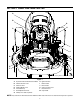
SECTION 4: KNOW YOUR LAWN TRACTOR A B G H C BRAKE I J D K L E F M NOTE: Steering Wheel not shown for clarity.
Throttle Control Lever Ignition Switch The throttle control lever is located on the left side of the tractor’s dash panel. This lever controls the speed of the engine. When set in a given position, the throttle will maintain a uniform engine speed. See Figure 4. WARNING: Never leave a running machine unattended. Always disengage the PTO, set parking brake, stop engine and remove key to prevent unintended starting.
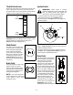
Hour Meter Electric PTO (Power Take-off) Knob Located in the center of the tractor’s console, the hour meter operates whenever the engine is running and records the actual hours of tractor operation. See Figure 6. To engage the power to the cutting deck or other (separately available) attachments, pull outward on the PTO knob. Push the PTO knob inward to disengage the power to the cutting deck.
Seat Adjustment Lever Deck Lift Lever To adjust the seat forward or backward, slide the seat adjustment lever to the left and reposition the seat to the desired position. Once a comfortable position is found, release the seat adjustment lever to lock the seat in place. Refer to Seat Adjustment on page 18 of this manual for more detailed instructions. Found on your tractor’s right fender, the deck lift lever is used to change the height of the cutting deck.
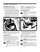
NOTE: Upon starting the engine, a metallic ticking may occur. This is caused by the hydraulic lifter leakdown during storage. Run the engine for five minutes. The noise will normally cease in the first minute. If noise continues, run the engine at mid-throttle for twenty minutes. If noise persists, have the engine serviced by your Cub Cadet dealer. Shoulder Screws Flat Washer NOTE: Do NOT leave the choke control on while operating the tractor.
• • Setting The Cruise Control Briefly depress the brake pedal to release the parking brake. Move the throttle lever into the FAST (rabbit) position. To travel FORWARD, slowly depress the upper portion of the drive pedal forward until the desired speed is achieved. See Figure 8. NOTE: The cruise control feature should only be utilized while traveling in the forward direction. • Brake Pedal • • • Slowly depress the upper portion of the drive pedal until the desired speed is achieved.
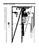
Moving The Tractor Manually Front View Your tractor’s transmission is equipped with a hydrostatic relief valve for occasions when it is necessary to move the tractor manually. Opening this valve permits the fluid in the transmission to bypass its normal route, allowing the rear tires to "freewheel." To engage the hydrostatic relief valve, proceed as follows: • Pull Out ON Push In OFF Locate the hydrostatic bypass rod in the rear of the tractor. See Figure 9.
Mulching Carriage Screw Model 1515 & 1517 lawn tractors come equipped with a mulch kit which incorporates special blades, already standard on your tractor, in a process of recirculating grass clippings repeatedly beneath the cutting deck. The ultra-fine clippings are then forced back into the lawn where they act as a natural fertilizer. Observe the following points for the best results when mulching. • • • • Never attempt to mulch if the lawn is damp.
Troubleshooting 3. Low Idle Speed Setting: Place the throttle control into the “idle” or “slow” position. Set the low idle speed to 1200 RPM* (± 75 RPM) by turning the low idle speed adjusting screw in or out. Check the speed using a tachometer. If engine troubles are experienced that appear to be fuel system related, check the following areas before adjusting the carburetor. • Make sure the fuel tank is filled with clean, fresh gasoline.
• • If the tractor does not come to a complete stop when the brake pedal is completely depressed, or if the tractor’s rear wheels can roll with the parking brake applied, the brake is in need of adjustment. The brake disc can be found on the right side of the transmission in the rear of the tractor. Adjust if necessary as follows. • Looking at the transmission from the right side of the tractor, locate the compression spring and brake disc. See Figure 16.
Front tire toe-in can be measured as follows: Hex Nut and Lock Washer • • Pivot Bar Axle • • • Place the steering wheel in position for straight ahead travel. In front of the axle, measure the distance horizontally from the inside of the left rim to the inside of the right rim. Note the distance. Behind the axle, measure the distance horizontally from the inside of the left rim to the inside of the right rim. Note the distance.
• • • • • • Allow the engine a few minutes to rest after operation. This will give the oil time to drain into the crankcase sump and result in a more accurate dipstick reading. Clean the area around the oil fill cap/dipstick to prevent debris from entering the crankcase. Remove the oil fill cap/dipstick by unthreading it (counterclockwise) and lifting it out of the oil fill tube. Wipe the dipstick clean before pushing it back into the oil fill tube. Do NOT thread the cap back onto the fill tube.
• • • Grasp the side panel just behind the grille and pull outward to release the side panel from the tapered bushings on the grille. Slide the side panel forward and out of the groove in the dash panel. • Draining the Oil • Run the engine for a few minutes to allow the oil in the crankcase to warm up. Warm oil will flow more freely and carry away more of the engine sediment which may have settled at the bottom of the crankcase. Use care to avoid burns from hot oil.
Air Filter The engine is equipped with a replaceable, high density paper air cleaner element and an oiled, foam precleaner which surrounds the paper element. See Figure 21. Always examine the air cleaner before starting the engine. Check for a buildup of dirt and debris around the air cleaner system. Keep this area clean. Also check for loose or damaged components. Replace all bent or damaged air cleaner components.
NOTE: Refer to the Attachments & Accessories table Visually inspect the filter periodically for a build-up of residue inside the filter body, and for a dirty element which can be indicated by discoloration. Replace the fuel filter when dirty. found on page 32 of this manual for the proper spark plug type. • • • • • Lift the tractor’s hood and locate the spark plug wire on the front, right area of the engine. Carefully pull the spark plug wire boot off of the spark plug.
Pivot Points & Linkage Lubricate all the pivot points on the drive system, parking brake and lift linkage at least once a season with light oil. Deck Wheels Each of the tractor deck’s front gauge wheels is equipped with a grease fitting. Lubricate with a grease gun after every 25 hours of tractor operation Front Wheels Each of the front wheel axles and rims is equipped with a grease fitting. See Figure 24. Lubricate with a grease gun after every 25 hours of tractor operation.
Cutting Blades The blade can be tested by balancing it on a round shaft screwdriver. Grind metal from the heavy side until it balances evenly. WARNING: Be sure to shut the engine off, remove ignition key, disconnect the spark plug wire(s) and ground against the engine to prevent unintended starting before removing the cutting blade(s) for sharpening or replacement. Protect your hands by using heavy gloves or a rag to grasp the cutting blade.
Charging If the unit has not been put into use for an extended period of time, charge the battery with an automotivetype 12-volt charger for a minimum of one hour at six amps. Support Pin WARNING: Batteries give off an explosive gas while charging. Charge battery in a well ventilated area and keep away from an open flame or pilot light as on a water heater, space heater, furnace, clothes dryer or other gas appliances.
Model 1515 Electric PTO Clutch PTO Idler Bracket (mounted on deck) Deck/PTO belt Left Hand Pulley (beneath belt guard) Right Hand Pulley (beneath belt guard) Deck Idler Pulleys Figure 28 Electric PTO Clutch PTO Idler Bracket (mounted on tractor) Left Hand Pulley Model 1517 Deck belt (Bottom) PTO belt (Top) Right Hand Pulley (beneath belt guard) Deck Idler Pulley Center Pulley Self-Tapping Screws NOTE: Left hand belt cover not shown for clarity.
NOTE: Proper removal of the drive belt requires the • removal of several tractor components. Read through the following procedure prior to attempting it to determine if you feel you could successfully complete it. If you don’t, see your Cub Cadet dealer to have the belt changed. • IMPORTANT: Note the routing of the lower drive belt around all the pulleys and the belt keepers (if present) BEFORE performing the following steps.
Hydrostatic Transmission The hydrostatic transmission is sealed at the factory and is maintenance free. The fluid level cannot be checked nor can the oil be changed. Always keep the area around the transmission cooling fan free of grass and debris at all times. SECTION 9: OFF-SEASON STORAGE Clean and lubricate the tractor as instructed in Section 7: MAINTAINING YOUR LAWN TRACTOR on page 19 of this manual before storing for an extended period.
SECTION 11: TROUBLESHOOTING Trouble Possible Cause(s) Corrective Action Engine fails to start PTO knob engaged. Parking brake not engaged. Spark plug wire(s) disconnected. Throttle control lever not in correct starting position. Choke not activated Fuel tank empty, or stale fuel. Blocked fuel line. Faulty spark plug. Engine flooded. Unit running with CHOKE applied. Spark plug wire loose. Blocked fuel line or stale fuel. Place knob in disengaged (OFF) position. Engage parking brake.
SECTION 12: SPECIFICATIONS 1515 1517 3 gallons (11.4 liters) 3 gallons (11.4 liters) 4 pints / 64 oz. (1.9 liters) 4 pints / 64 oz. (1.9 liters) 4.9 pints / 78.8 oz. (2.3 liters) 4.9 pints / 78.8 oz. (2.3 liters) Hydro-Gear 311-0710 Hydro-Gear 311-0710 22.2:1 22.2:1 Forward Speed 0 m.p.h. - 5.5 m.p.h. 0 m.p.h. - 5.5 m.p.h. Reverse Speed 0 m.p.h. - 2.5 m.p.h. 0 m.p.h. - 2.5 m.p.h. Kohler CV15 Kohler CV490 Single Single Bore 3.55 in. (90 mm) 3.54 in. (90 mm) Stroke 2.64 in.
SECTION 13: ATTACHMENTS & ACCESSORIES The following attachments and accessories are compatible for Model 1515 & Model 1517. See your Cub Cadet dealer or the retailer from which you purchased your tractor for information regarding price and availability. NOTE: Cub Cadet lawn tractor models 1515 and 1517 are NOT designed for use with any type of groundengaging attachments (e.g. tiller or mulboard plow). Use of this type of equipment WILL void the tractor’s warranty.
777I00005 777I00003 777D01782 777I00004 STOP IGNITION 33 WARNING SEAT ADJUSTER RELEASE 777D04541 777S00007 777I20310 777D05387 D03263 D03263 1500 777D03264 LEFT SIDE 777D03263 RIGHT SIDE (2) 777X40079 777D05447 D03264 777D05479 777D05478 777D05448 777I20314 LABEL MAP
KOHLER CO. FEDERAL AND CALIFORNIA EMISSION CONTROL SYSTEMS LIMITED WARRANTY UTILITY AND LAWN AND GARDEN ENGINES The U.S. Environmental Protection Agency (EPA), the California Air Resources Board (CARB), and Kohler Co. are pleased to explain the Federal and California Emission Control Systems Warranty on your small off-road equipment engine. For California, engines produced in 1995 and later must be designed, built and equipped to meet the state’s stringent anti-smog standards.
CUB CADET LLC MANUFACTURER’S ONE YEAR LIMITED WARRANTY (COMMERCIAL USE) The limited warranty set forth below is given by CUB CADET LLC (“CUB CADET”) with respect to new merchandise purchased and used in the United States, its possessions and territories.
CUB CADET LLC MANUFACTURER’S LIMITED WARRANTY (RESIDENTIAL USE) The limited warranty set forth below is given by CUB CADET LLC (“CUB CADET”) with respect to new merchandise purchased and used in the United States, its possessions and territories.