Safe Operation Practices • Set-Up • Operation • Maintenance • Service • Troubleshooting • Warranty Operator’s Manual Front Tine Tiller — 340 Series WARNING READ AND FOLLOW ALL SAFETY RULES AND INSTRUCTIONS IN THIS MANUAL BEFORE ATTEMPTING TO OPERATE THIS MACHINE. FAILURE TO COMPLY WITH THESE INSTRUCTIONS MAY RESULT IN PERSONAL INJURY. CUB CADET LLC, P.O. BOX 361131 CLEVELAND, OHIO 44136-0019 Printed In USA Form No.
1 To The Owner Thank You Thank you for purchasing a Cub Cadet Garden Tiller. It was carefully engineered to provide excellent performance when properly operated and maintained. Please read this entire manual prior to operating the equipment. It instructs you how to safely and easily set up, operate and maintain your machine. Please be sure that you, and any other persons who will operate the machine, carefully follow the recommended safety practices at all times.
2 Important Safe Operation Practices WARNING! This symbol points out important safety instructions which, if not followed, could endanger the personal safety and/or property of yourself and others. Read and follow all instructions in this manual before attempting to operate this machine. Failure to comply with these instructions may result in personal injury. When you see this symbol.
c. When practical, remove gas-powered equipment from the truck or trailer and refuel it on the ground. If this is not possible, then refuel such equipment on a trailer with a portable container, rather than from a gasoline dispenser nozzle. 11. After striking a foreign object, stop the engine, disconnect the spark plug wire and ground against the engine. Thoroughly inspect the machine for any damage. Repair the damage before starting and operating. d.
9. If the fuel tank has to be drained, do this outdoors. 10. Observe proper disposal laws and regulations for gas, oil, etc. to protect the environment. 11. According to the Consumer Products Safety Commission (CPSC) and the U.S. Environmental Protection Agency (EPA), this product has an Average Useful Life of seven (7) years, or 130 hours of operation.
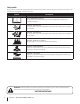
Safety Symbols This page depicts and describes safety symbols that may appear on this product. Read, understand, and follow all instructions on the machine before attempting to assemble and operate. Symbol Description READ THE OPERATOR’S MANUAL(S) Read, understand, and follow all instructions in the manual(s) before attempting to assemble and operate WARNING— ROTATING TINES Do not put hands or feet near rotating parts. Contact with the rotating parts can amputate hands and feet.
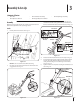
3 Assembly & Set-Up Contents of Carton • One Tiller • One Handlebar Assembly • One Operator’s Manual • One Engine Operator’s Manual Assembly 3. One Depth Gage Assembly Remove the hex screw and bell washer from the right side of the frame. Hold the cable guide bracket on the left side of frame as it will fall when the bolt is removed. Step 1 in Fig. 3–3. References to the right and left side of tiller are determined from behind the equipment in the operating position. Handle 1.
7. Locate the carriage screw, bell washer and hand knob packed with your tiller. 8. Insert the carriage screw through the bracket on the handle, bell washer, handle brace and into the hand knob. See Fig. 3–4. 9. Select one of the three handle height positions (three notches in the welded handle bracket) and tighten the hand knob to secure the handle in the desired position. See Fig. 3–4. Return to the lower handle and tighten the hex bolt securely. Depth Gauge 1.
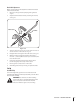
Clutch Cable Adjustment Before operating the tiller the adjustment of the forward clutch cables must be checked. 1. Disconnect and ground the spark plug wire against the engine. 2. Adjust the forward clutch cable by loosening the hex nut. See Fig. 3-8. Cable Collar Hex Nut Figure 3-8 3. Turn the cable collar section one or two turns to increase or decrease tension on the cable. See Fig. 3-8. 4. Retighten the lock nut against the cable collar. See Fig. 3-8. 5.
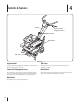
4 Controls & Features Handle Forward Tine Engagement Lever Handle Knob Depth Stake Tiller Tines Engine Controls Tiller Tines See the separate Engine Operator’s Manual for information and functions of the engine controls. Tilling tines are used to cultivate, furrow and prepare your garden for seeding. Forward Tine Engagement Lever Handle Knob The forward tine control lever is located beneath the upper section of the handle. Squeezing the lever against the handle engages the tine drive.
5 Operation Starting & Stopping the Engine WARNING! Read, understand, and follow all the instructions and warnings posted on the machine and in this manual before operating. Yoke to Back Place the wheel yoke so that wheels are toward the rear — closest to depth stake — for deep tilling and cultivating. See Fig. 5-2. WARNING! Be sure no one is standing in front of the tiller while the engine is running or being started. 1.
Handle Pressure Cultivating Procedures Further control of the tilling depth and travel speed can be obtained by variation of pressure on the handles. For cultivating, a two to three inch depth is desirable. The tine width can be reduced to 13 inches by removing the outer tines completely from the tiller. See the Maintenance & Adjustments Section for instructions on removing the tines. A downward pressure on the handles will reduce the working depth and increase the forward speed.
6 Maintenance & Adjustments WARNING! Disconnect the spark plug wire and ground it against the engine before performing any repairs. Maintenance Engine Tines With the outer tines installed, the working width of the machine is 24 inches. This width may be expanded to 26 inches by removing the clevis and cotter pins, sliding each outer tine outward away from the center of the tiller and re-securing the pins in the holes provided. See Fig. 6-1.
8 Service Belt Replacement 4. Your tiller has been engineered with a belt made of special material (Kevlar Tensile) for longer life and better performance. It should not be replaced with an off-the-shelf belt. Order all belts through you authorized service dealer. 1. Disconnect and ground the spark plug wire against the engine. 2. Remove the belt cover from the left side of the tiller by removing the two hex washer screws and the lock nut and washer. See Fig. 7–1.
9 Troubleshooting Problem Tines do not engage Cause Remedy 1. Foreign object lodged in tines 1. Dislodge foreign object 2. Tine clevis pin(s) missing 2. Replace tine clevis pin(s) 3. Pulley and idler not in correct adjustment 3. Take tiller to authorized service dealer 4. Not shifting properly 4. Refer to the Controls & Features Section for proper shifting procedures 5. Control cable not adjusted properly 5. Adjust control cable 6. Belt worn and/or stretched 6.
10 Replacement Parts Component Part Number and Description 642-0002 642-0003 Inner Right Hand Tine Inner Left Hand Tine 642-0005 642-0004 Outer Left Hand Tine Outer Right Hand Tine 714-04043 911-0415 Cotter Pin Clevis Pin 714-0428 Drive Belt 946-0918 Forward Cable 734-04623 Wheels, 8” x 1.75” Phone (800) 965-4CUB to order replacement parts or a complete Parts Manual (have your full model number and serial number ready). Parts Manual downloads are also available free of charge at www.cubcadet.
Notes 10 17
CUB CADET LLC MANUFACTURER’S LIMITED WARRANTY FOR EDGERS, STRING TRIMMERS & TILLERS The limited warranty set forth below is given by Cub Cadet LLC with respect to new merchandise purchased and used in the United States, its possessions and territories, and by MTD Products Limited with respect to new merchandise purchased and used in Canada and/or its territories and possessions. c.
Medidas importantes de seguridad • Configuración • Funcionamiento • Mantenimiento Servicio • Solución de problemas • Garantía Manual de Operación Cultivadora de dientes frontales – Serie 340 ADVERTENCIA LEA Y RESPETE TODAS LAS NORMAS DE SEGURIDAD E INSTRUCCIONES INCLUIDAS EN ESTE MANUAL ANTES DE PONER EN FUNCIONAMIENTO ESTA MÁQUINA. SI NO RESPETA ESTAS INSTRUCCIONES PUEDE PROVOCAR LESIONES PERSONALES. CUB CADET LLC, P.O.
1 Al propietario Gracias Gracias por comprar una cultivadora de jardín Cub Cadet. La misma ha sido diseñada cuidadosamente para brindar excelente rendimiento si se la opera y mantiene correctamente. Por favor lea todo este manual antes de operar el equipo. Le indica cómo configurar, operar y mantener la máquina con seguridad y fácilmente. Por favor cerciórese de que usted o cualquier otra persona que opere la máquina siga cuidadosamente y en todo momento las prácticas de seguridad recomendadas.
2 Medidas importantes de seguridad ¡ADVERTENCIA! La presencia de este símbolo indica que se trata de instrucciones importantes de seguridad que se deben respetar para evitar poner en peligro su seguridad personal y/o material y la de otras personas. Lea y siga todas las instrucciones de este manual antes de poner en funcionamiento esta máquina. Si no respeta estas instrucciones puede provocar lesiones personales. Cuando vea este símbolo.
Manejo seguro de la gasolina: Para evitar lesiones personales o daños materiales tenga mucho cuidado cuando trabaje con gasolina. La gasolina es sumamente inflamable y sus vapores pueden causar explosiones. Si se derrama gasolina encima o sobre la ropa se puede lesionar gravemente ya que se puede incendiar. Lávese la piel y cámbiese de ropa de inmediato. a. Utilice sólo los recipientes para gasolina autorizados. b.
4. 5. 6. 7. 8. 9. 10. 11. Antes de limpiar, reparar o inspeccionar la máquina, detenga el motor y asegúrese de que los dientes y todas las partes móviles se hayan detenido. Desconecte el cable de la bujía y póngalo haciendo masa contra el motor para evitar que se encienda accidentalmente. No cambie la configuración del regulador del motor ni lo opere a sobrevelocidad. El regulador del motor controla la velocidad máxima de funcionamiento seguro del motor.
Símbolos de Seguridad Esta página describe los símbolos y figuras de seguridad internacionales que pueden aparecer en este producto. Lea el manual del operador para obtener la información terminada sobre seguridad, reunirse, operación y mantenimiento y reparación. Símbolo Descripción LEA EL MANUAL DEL OPERADOR (S) Lea, entienda, y siga todas las instrucciones en el manual (es) antes de intentar reunirse y funcionar. LA ADVERTENCIA — LOS DIENTES ROTATIVO No ponga manos o pies cerca del giro de partes.
3 Montaje y Configuración Contenido de la caja de cartón • Una cultivadora • Un conjunto de barra de control • Un Manual de operación • Un Manual de operación del motor Montaje 3. Retire el tornillo hexagonal y la arandela campana del lado derecho del bastidor. Sostenga la ménsula de la guía del cable del lado izquierdo del bastidor ya que se caerá al quitar el perno. Paso 1 en la Fig. 3–3.
7. Ubique el perno de carro, la arandela de campana y la perilla de mano empaquetados con su cultivadora. 8. Inserte el perno de carro a través del soporte soldado de la manija, la arandela campana, la traba de la manija, y dentro de la perilla de mano. Vea la Fig. 3-4. 9. Seleccione una de las tres posiciones para la altura de la manija (tres muescas en la ménsula soldada de la manija), y ajuste la perilla de mano para fijar la manija en la posición deseada. Vea la Fig. 3-4.
Ajustes Ajuste del cable De vez en cuando puede ser necesario ajustar la tensión en el cable de la participación de dientes hacia adelante. 1. Desconecte y el suelo cable de la bujía contra el motor. 2. Ajuste el cable del embrague hacia delante, aflojando la tuerca hexagonal. Véase la figura. 3-8. tuerca cable cuello Figura 3-8 3. A su vez la sección del cable cuello una o dos vueltas para aumentar o disminuir la tensión en el cable. Véase la figura. 3-8. 4.
4 Controles y Características Mango Marcha directa de dientes Palanca de enganche Perilla de la manija Estaca de profundidad Dientes de la cultivadora Controles del motor Figura 4-1 Consulte el Manual de operación del motor, por separado, para obtener información adicional y detalles sobre las funciones de los controles del motor. Palanca de enganche de marcha hacia adelante de los dientes La palanca de control de los dientes hacia adelante está ubicada debajo de la parte superior de la manija.
5 Funcionamiento Arranque y detención del motor ¡ADVERTENCIA! Lea, comprenda y siga todas las instrucciones y advertencias que se encuentran en la máquina y en este manual antes de operarla. Retén hacia atrás Coloque el retén de las ruedas de manera que las ruedas están hacia atrás (punto más cercano a la estaca de profundidad) para labranza profunda y cultivo. Vea la Fig. 5-2.
Presión de las manijas Procedimientos para realizar tareas de labranza Se puede obtener un mayor control de la profundidad de la labranza y de la velocidad de recorrido variando la presión sobre las manijas. La presión hacia abajo sobre las manijas reduce la profundidad del trabajo y aumenta la velocidad de marcha directa. La presión hacia arriba sobre las manijas aumenta la profundidad del trabajo y reduce la velocidad de marcha directa.
6 Mantenimiento y Ajustes ¡ADVERTENCIA! Desconecte el cable de la bujía y tierra contra el motor antes de realizar cualquier reparación. Mantenimiento Motor Dientes Con los dientes exterior instalado, el ancho de trabajo de la máquina es de 24 pulgadas. Esta anchura se puede ampliar a 26 pulgadas por la eliminación de la horquilla y pasadores, correderas cada diente hacia el exterior exterior del centro de la caña del timón y volver a asegurar los pasadores en los orificios. Véase la figura. 6-1.
8 Servicio Cambio de correa 4. El diseño de la cultivadora incluye una correa de material especial (Kevlar Tracción) que le proporciona mayor duración y mejor rendimiento. No se la debe cambiar por una correa cualquiera. Pida todas las correas a través de su distribuidor de servicio autorizado. 1. Desconéctelos y haga masa con el cable de la bujía contra el motor. 2.
8 Solución de problemas Problema Los dientes no enganchan Causa Remedio 1. Hay un objeto extraño entre los dientes 1. Desaloje el objeto extraño. 2. Falta la o las chavetas de horquilla de los dientes. 2. Cambie la o las chavetas de horquilla de los dientes. 3. La polea y la polea loca necesitan ajuste. 3. Lleve la unidad al distribuidor autorizado de mantenimiento. 4. Dificultad en el cambio de marcha. 5. El cable de control no está ajustado correctamente. 6. Correa desgastada y/o estirada. 4.
Notas 16 9
Sección 9 — Notas 17
GARANTÍA LIMITADA DE CUB CADET LLC PARA BORDEADORA DE CÉSPED, CONTEMPORIZADOR DE CUERDA Y CULTIVADORA DE DIENTES TRASEROS La siguiente garantía limitada es otorgada por Cub Cadet LLC con respecto a nuevos productos adquiridos y utilizados en Estados Unidos, sus posesiones territorios, y por MTD Products Limited con respecto a nuevos productos adquiridos y utilizados en Canadá y/o sus territorios y posesiones. d.