
Use and Care Manual


Assembly & Set-Up
3
7
Assembly
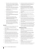
References to the right and left side of tiller are determined from
behind the equipment in the operating position.
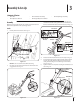
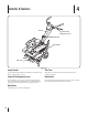
Handle
Forward Clutch Cable
Figure 3-1
NOTE:
2.
Figure 3-2
Remove the hex screw and bell washer from the right side
2
1
3
Hex Screw
Hex Screw
Bell Washer
Bell Washer
Cable Guide
Bracket
Handle
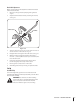
Figure 3-3
4.
5. Insert the bolt through the cupped washer, frame, handle
and into the cable guide bracket (note the notch in the
cable guide bracket goes over the flange on the frame.)
6. Tighten the bolt securely after securing the handle brace as
Carriage Screw
Handle Brace
Bell Washer
Hand Knob
Figure 3-4
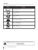
Contents of Carton