Important Safe Operation Practices • Assembly & Set-Up • Controls & Operation • Product Care Operator’s Manual Lawn Tractor & Garden Tractor Table of Contents Important Safe Operation Practices...................... 2 Product Care............................................................16 Assembly & Set-Up................................................... 7 Parts/Warranty............... See Separate Supplement Controls & Operation..............................................
Important Safe Operation Practices 2 WARNING This symbol points out important safety instructions which, if not followed, could endanger the personal safety and/or property of yourself and others. Read and follow all instructions in this manual before attempting to operate this machine. Failure to comply with these instructions may result in personal injury. When you see this symbol.
Slope Operation 7. Slopes are a major factor related to loss of control and tip-over accidents which can result in severe injury or death. All slopes require extra caution. If you cannot back up the slope or if you feel uneasy on it, do not mow it. For your safety, use the slope gauge included as part of this manual to measure slopes before operating this machine on a sloped or hilly area.
j. k. l. To reduce fire hazards, keep machine free of grass, leaves, or other debris build-up. Follow the “Post-Operation Tractor Care” instructions in the Product Care section. Clean up oil or fuel spillage and remove any fuel soaked debris. Never store the machine or fuel container inside where there is an open flame, spark or pilot light as on a water heater, space heater, furnace, clothes dryer or other gas appliances. Thoroughly inspect the machine for any damage.
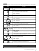
Safety Symbols This page depicts and describes safety symbols that may appear on this product. Read, understand, and follow all instructions on the machine before attempting to assemble and operate. Symbol Description READ THE OPERATOR’S MANUAL(S) Read, understand, and follow all instructions in the manual(s) before attempting to assemble and operate DANGER — ROTATING BLADES Never carry passengers. Never carry children, even with the blades off.
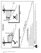
Section 2 — Important Safe Operation Practices Figure 1 line Figure 2 (TOO STEEP) 15°/25% Slope Do not operate machine on slopes in excess of 15 degrees. All slopes require extra caution. If you cannot back up the slope or if you feel uneasy on it, do not mow it. Always mow up and down slopes, never across the face of slopes. WARNING! Slopes are a major factor related to tip-over and roll-over accidents which can result in severe injury or death. To check the slope, proceed as follows: 1.
Assembly & Set-Up 2 Thank You Thank you for purchasing this product. It was carefully engineered to provide excellent performance when properly operated and maintained. Please read this entire manual prior to operating the equipment. It instructs you how to safely and easily set up, operate and maintain your machine. Please be sure that you, and any other persons who will operate the machine, carefully follow the recommended safety practices at all times.
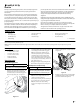
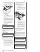
4. Then with the previously removed shoulder bolts (a) and flange lock nuts (b) secure one side of the seat and seat bracket. While supporting the seat, remove the Phillips screwdriver and secure the other side of the seat. Be careful not to crimp or damage the wire harness while installing the seat. See Figure 2-3. Installing the Hood Collar (If necessary) There are three (3) alignment posts (a) on the hood collar (b) that line up with corresponding alignment holes (c) in the hood (d). See Figure 2-6.
Installing the Plenum (If necessary) Installing the Dash Cap (If necessary) Installing the Front Bumper (If necessary) Note: Be careful not to damage the headlight harness when installing the plenum. To install the dash cap (a), line up the tabs (b) on the dash cap (a) with the holes in the upper dash as shown in Figure 2-14. Slide the tabs (b) into the holes in the upper dash and push forward (c) on the dash cap (a) to lock into place.
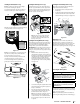
1. Remove the plastic cover, if present, from the positive battery terminal and attach the red cable to the positive battery terminal (+) with the bolt (a) and hex nut (b). See Figure 2-18. 4. Check the wheels for contact or excessive clearance with the surface below. The deck wheels should have between ¼” and ½” clearance above the ground. Proceed as follows to adjust the wheels: (b) (b) (a) (c) a. Raise the deck lift handle to its highest setting. b.
Controls & Operation Choke Control (If equipped) (E) The choke control is located on the dash panel to the right of the throttle/choke or throttle control and controls the position of the engine choke. Pull the knob out/ up to choke the engine; push the knob in/down to open the choke. (M) (L) (C) (G) (D) (E) (K) (P) (H) 3 (A) (B) (F) (I) Deck Lift Lever (F) Electric PTO tractors (N) (O) Manual PTO tractors (Q) (J) Figure 3-1 Note: This Operator’s Manual covers several models.
PBS (Push Button Start)/Service Minder & Hour Meter w/ Bluetooth® (If equipped) INSERT KEY AND PUSH START / STOP BUTTON (HOUR METER AND LIGHTS COME ON) TO START: DEPRESS BRAKE, PUSH& HOLD START/STOP BUTTON FOR 1.5 SEC. PBS tractors come with TO TURN OFF : PRESS or without Bluetooth®. If equipped, connect your Bluetooth® enabled LCD service minder & hour meter to your smartphone by downloading the App for your Bluetooth® capable Android or iOS device.
Operator’s Manual. Low Oil (If equipped) The letters “LO” followed by the letters “OIL”, then followed by the meter’s accumulated time will indicate the tractor is low on oil. When an engine is not running and immediately after the engine is started the oil pressure may be low. This can trigger the “LO” “OIL” text. This is normal. If the low oil indication persists stop the tractor immediately and check the engine oil level as instructed in the Engine Operator’s Manual.
PBS Ignition 1. Place the PTO in the DISENGAGED (OFF) position. 2. Fully engage the tractor’s brake. 3. Move the throttle into the FAST 4. Insert the ignition key and press the ignition key. position. Note: When operating the tractor be certain that the throttle lever is always in the FAST position. Operating with the throttle at less than full throttle may lead to shortened battery life. Stopping the Engine 3. (c) at Press the REVERSE PUSH BUTTON the top, right corner of the ignition module.
Driving On Slopes Refer to the SLOPE GAUGE on page 6 to help determine slopes where you may operate the tractor safely. WARNING Do not mow on inclines with a slope in excess of 15 degrees (a rise of approximately 2-1⁄2 feet every 10 feet). The tractor could overturn and cause serious injury. • Mow up and down slopes, NEVER across. • Exercise extreme caution when changing direction on slopes. • Watch for holes, ruts, bumps, rocks, or other hidden objects. Uneven terrain could overturn the machine.
4 Product Care Maintenance Schedule Before Each use Check/Clean Engine Intake Screens & Cooling Fans * Check/Clean Exhaust Manifold, Muffler Pipe & Muffler Shields * Check/Clean Hood/Dash Panel Louvers * Check/Clean Top & Underside of Deck, Under and Around Spindle Covers & Belt Area * Check/Clean Around Fuses, Wiring and Wiring Harnesses * Check/Clean Around Transmission, Axle and Fans * Check Engine Oil Level Check Air Filter for Dirty After First 5 Hours Every 10 Hours Every 25 Hours Every 50 Hours
Note: This Operator’s Manual covers several models. Tractor features may vary by model. Not all features in this manual are applicable to all tractor models and the tractor depicted may differ from yours. WARNING Before inspecting or cleaning always disengage the PTO, set the parking brake, stop the engine and remove the key to prevent unintended starting. 8. Remain in the operator’s position with the deck engaged for a minimum of two minutes, allowing the underside of the deck to thoroughly rinse. 9.
Maintenance Charging Run the engine for a short time to warm the engine oil. The oil will flow more freely and carry away more impurities. Use care to avoid burns from hot oil. 2. Open the tractor’s hood and locate the oil drain port on the side of the engine. 3. Place an appropriate oil collection container with at least a 2.5 quart capacity below the opening of the oil drain tube, to collect the used oil. Remove the oil fill cap/dipstick from the oil fill tube. 4.
Lubrication ydrostatic Transmission DANGER Bearing failures and overheating can result in fire/ Always follow the instructions in this manual regarding lubrications locations and intervals. Contact your authorized dealer with any questions about the lubrication locations and intervals or any unusual noises coming from any areas a bearing may be located.
The deck wheels should be approximately 1⁄4-1⁄2” above the ground when the deck is set in the desired height setting. To adjust the deck wheels see the Assembly & Set-Up section for instructions. 4. Refer to the Assembly & Set-Up section of this manual for seat adjustment instructions. Before operating the tractor, make sure the seat is engaged in the seat-stop. Engage the parking brake. Stand behind the machine and pull back on seat until it clicks into place.
9. Pivot the wrench forward to move the deck drive pulley forward. See Figure 4-3. WARNING Avoid pinching injuries. Never place your fingers on the idler spring or between the belt and a pulley while installing the belt. 10. Carefully remove the belt from around the PTO pulley. 11. Looking at the deck from the left side of the tractor, locate the bow-tie pin on the rear left side of the deck. See Figure 4-4. Cutting Blades 5.
5. 6. 46” Decks 7. 8. 9. Retighten idler pulleys, if loosened earlier. Remount the spindle covers if removed earlier. Re-install the deck make sure the belt remains routed around the pulleys as instructed. On manual PTO units, re-install the engine pulley keeper rod and the PTO cable. Pull the right side of the belt and place the narrow V side of the belt into the PTO pulley. See Figure 4-11.
Medidas importantes de seguridad • Armado e instalación • Controles y funcionamiento • Cuidado del producto Manual del Operador Tractor cortacésped y tractor de jardín Índice Medidas importantes de seguridad............................... 2 Armado e Instalación ..................................................... 7 Controles y Funcionamiento........................................ 11 Cuidado del producto.................................................... 16 Piezas/Garantía.................
2 Importantes medidas de seguridad ¡ADVERTENCIA! Este símbolo indica instrucciones de seguridad importantes que, de no seguirse, pueden poner en peligro su seguridad personal y/o material y la de otras personas. Lea y cumpla todas las instrucciones de este manual antes de intentar hacer funcionar esta máquina. Si no sigue estas instrucciones, puede provocar lesiones personales.
26. Su máquina está diseñada para cortar césped residencial normal de una altura no mayor a 10 pulgadas. No intente cortar césped demasiado crecido, seco (como un pastizal) ni pilas de hojas secas. El césped o las hojas secas pueden entrar en contacto con el escape del motor y/o acumularse en la plataforma de corte presentando un potencial peligro de incendio. 7. Evite arrancar o detenerse en una pendiente. Si las ruedas pierden tracción, desacople las cuchillas y descienda la pendiente lentamente.
Servicio Manejo seguro de la gasolina: Servicio general 1. 1. Nunca encienda el motor en espacios cerrados o en una zona con poca ventilación. El escape del motor contiene monóxido de carbono, un gas inodoro y letal. 2. Antes de limpiar, reparar o inspeccionar la máquina, compruebe que las cuchillas y todas las piezas móviles se hayan detenido. Desconecte el cable de la bujía y póngalo haciendo masa contra el motor para evitar que se encienda accidentalmente.
Símbolos de seguridad En esta página se presentan y describen los símbolos de seguridad que pueden aparecer en este producto. Lea, comprenda y siga todas las instrucciones incluidas en la máquina antes de intentar armarla y hacerla funcionar. Símbolo Descripción LEA LOS MANUALES DEL OPERADOR Lea, entienda y siga todas las instrucciones incluidas en los manuales antes de intentar armar la unidad y hacerla funcionar PELIGRO — CUCHILLAS GIRATORIAS Nunca lleve pasajeros.
6 Sección 2 — Importantes medidas de seguridad Figura 1 Línea ntos de pu Pendiente de 15°/ ¡ADVERTENCIA! Las pendientes son uno de los principales factores asociados a los accidentes por tumbos y vuelcos que pueden producir lesiones graves o la muerte. No utilice la máquina en pendientes de más de 15°. Todas las pendientes exigen precaución adicional. Si no puede retroceder por la pendiente o si no se siente seguro, no realice ningún corte.
2 Armado e Instalación Muchas gracias Si corresponde, la información sobre las prueba de potencia utilizada para determinar la potencia nominal del motor equipado en esta máquina se puede consultar en www.opei. org o en el sitio web del fabricante del motor. Gracias por comprar este producto. Ha sido cuidadosamente diseñado para brindar excelente rendimiento si se lo hace funcionar y se lo mantiene correctamente. Por favor lea todo este manual antes de hacer funcionar el equipo.
3. Gire el asiento hasta la posición deseada y asegúrelo en su lugar con los tornillos de reborde (a) y las tuercas de seguridad con brida (b) que extrajo antes. Tenga cuidado de no doblar o dañar el cableado mientras instala el asiento. Vea la Figura 2-3. Instalación del collar de la capucha (si es necesario) Hay tres (3) postes de alineación (a) en el cuello de la campana (b) que se alinean con los agujeros de alineación correspondientes (c) en la campana (d). Ver Figura 2-6.
Instalación del Plenum (si es necesario) Figura 2-14.Instalación de la cubierta del tablero (si Nota: Tenga cuidado de no dañar el arnés del faro cuando instale el plenum. Para instalar el plenum (a) en la campana (b), primero inserte las lengüetas traseras (c) como se muestra en Figura 2-11. corresponde) Para instalar la cubierta del tablero (a), alinee las lengüetas (b) de la cubierta del tablero (c) con los orificios de la parte superior del tablero como se muestra en Figura 2-15.
3. Retire la cubierta plástica, si está presente, del borne positivo de la batería y una el cable rojo al borne positivo de la batería (+) utilizando el perno (a) y la tuerca hexagonal (b). Vea la Figura 2-19. Ajuste de las ruedas de la plataforma ADVERTENCIA Mantenga las manos y los pies alejados de la abertura de descarga de la plataforma de corte.
Controles y Funcionamiento Control del cebador (si está equipado) (E) El control del cebador está ubicado sobre el tablero de instrumentos a la derecha del control del acelerado/ cebador o del acelerado y controla la posición del cebador del motor. Tire de la perilla hacia afuera/arriba para cebar el motor; empuje la perilla hacia adentro/abajo para abrir el cebador.
PBS (arranque con botón pulsador)/avisador de servicio y medidor horario con Bluetooth® (si está equipado) Los tractores con PBS pueden venir equipados con o sin Bluetooth®. Si está incluido, conecte su avisador de servicio y medidor horario activado por Bluetooth® a su teléfono inteligente descargando la aplicación para su dispositivo Android o iOS compatible con Bluetooth®.
Función "Nivel bajo de aceite" (si está incluida) Tapón del depósito de combustible (M) Las letras “LO” (nivel bajo) seguidas de las letras “OIL” (aceite), seguidas luego del tiempo acumulado del medidor indicarán que el tractor tiene poco aceite. Cuando un motor no está en funcionamiento e inmediatamente después de que el motor arranca, la presión de aceite puede estar baja. Esto puede activar el texto "LO" "OIL" (nivel bajo de aceite). Esto es normal.
Encendido con PBS 1. Coloque la PTO en la posición de DESACTIVACIÓN (OFF). 2. Aplique completamente el freno del tractor. 3. Mueva el acelerador a la posición FAST (velocidad rápida, representada por una liebre). 4. Inserte la llave de encendido y presiónela. NOTA: Cuando haga funcionar el tractor asegúrese de que la palanca del acelerador esté siempre en (rápida). Funcionar con el la posición FAST acelerador a menos de máxima velocidad puede acortar la vida útil de la batería.
Conducción en pendientes Consulte la sección INDICADOR DE PENDIENTE en la página 6 para determinar en qué pendientes puede operar el tractor de manera segura. ADVERTENCIA No corte en pendientes con una inclinación de más de 15° (elevación aproximada de 2-1⁄2 pies por cada 10 pies). El tractor podría darse vuelta y causar lesiones graves. • En las pendientes, corte hacia arriba y hacia abajo, NUNCA en forma transversal. • Tenga sumo cuidado al cambiar de dirección en una pendiente.
Cuidado del producto 4 Programa de Mantenimiento Antes de cada uso Compruebe/Limpie las Pantallas de Entrada de Motor y los Ventiladores de Enfriamiento * Revisar/Limpiar el Colector de Escape, el Silenciador y los Escudos del Silenciador * Compruebe/Limpie la Campana/Tablero Tableros * Compruebe/Limpie la parte superior y la parte inferior de la cubierta, debajo y alrededor de las cubiertas del eje y el área de la correa * Comprobar / limpiar alrededor de los fusibles, el cableado y los arneses de cable
NOTA: Este manual del operador abarca numerosos modelos. Las características del tractor pueden variar según los modelos. No todas las características que se incluyen en este manual se aplican a todos los modelos de tractor y la máquina que se ilustra aquí puede diferir de la suya. ADVERTENCIA Antes de realizar tareas de mantenimiento o reparaciones, desconecte la PTO, ponga el freno de mano, apague el motor y retire la llave para evitar el encendido accidental del motor.
Mantenimiento PRECAUCIÓN Motor Consulte el Manual del operador del motor para obtener información sobre las preguntas y los problemas relacionados con el motor. NOTA: El mantenimiento, reparación o reemplazo de los dispositivos y sistemas del control de emisiones, que corre por cuenta del cliente, puede realizarlo cualquier establecimiento o individuo especializado en reparaciones de motores. Los arreglos en garantía deben ser realizados por distribuidor autorizado.
Ajustes 2. Mida la distancia desde la parte externa de la punta de la cuchilla izquierda hasta el piso, y desde la parte externa de la punta de la cuchilla derecha hasta el piso. Las dos mediciones obtenidas deben ser iguales. Si no lo son, realice el siguiente paso. 3. Debajo de los guardabarros traseros dentro de las ruedas hay una varilla de ajuste de elevación para cada lado de la plataforma. Vea la Figura 4-5. 4.
Ajuste de las ruedas de la plataforma 3. Para almacenar motores entre 30 y 90 días es necesario tratarlos con un estabilizador de gasolina, y para almacenarlos durante más de 90 días se debe drenar el combustible para evitar deterioros y la formación de depósitos de goma en el sistema de combustible o en piezas fundamentales del carburador.
9. Pivote la llave hacia adelante para mover la polea de transmisión de la plataforma hacia adelante. Vea la Figura 4-3. ADVERTENCIA Evite las lesiones por compresión. Al instalar la correa, no coloque nunca los dedos en el resorte intermedio o entre la correa y una polea. 10. 11. Cuchillas de corte ADVERTENCIA Apague el motor y extraiga la llave de contacto antes de retirar las cuchillas de corte para afilarlas o reemplazarlas. Proteja sus manos utilizando guantes reforzados cuando sujete las cuchillas.
Plataformas de 46” 5. Vuelva a apretar las poleas locas, si se aflojaron anteriormente. 6. Vuelva a montar las cubiertas de los husillos se fueron retiradas. 7. Reinstale la plataforma y asegúrese de que la correa se haya pasado alrededor de las poleas como se indica. 8. En unidades con PTO manual, reinstale la varilla guardapolea del motor y el cable de la PTO. 9. Tire del lado derecho de la correa y coloque el lado V angosto de la correa en la polea de la PTO. Vea la Figura 4-11.